Eureka AIR delivers breakthrough ideas for toughest innovation challenges, trusted by R&D personnel around the world.

Piezoelectric energy collector and power generation equipment

A technology for piezoelectric energy and power generation equipment, which is applied to generators/motors, piezoelectric effect/electrostrictive or magnetostrictive motors, electrical components, etc. , low acquisition and conversion efficiency, etc., to achieve the effect of widening the frequency band and improving the acquisition and conversion efficiency

Inactive Publication Date: 2017-09-19
SYSU CMU SHUNDE INT JOINT RES INST +1
View PDF10 Cites 6 Cited by
  • Summary
  • Abstract
  • Description
  • Claims
  • Application Information

AI Technical Summary

Problems solved by technology

[0004] Based on this, it is necessary to provide a piezoelectric energy harvester and power generation equipment for the problems of single operating frequency, narrow frequency band, and low acquisition and conversion efficiency of the piezoelectric energy harvester.

Method used


Image

  • Piezoelectric energy collector and power generation equipment

Examples


Embodiment Construction

[0021] Embodiments of the present invention are described in detail below in conjunction with accompanying drawings:

[0022] It should be noted that when an element is “fixed” to another element, it may be directly on the other element or there may be an intervening element. When an element is referred to as being "connected to" another element, it can be directly connected to the other element or intervening elements may also be present. In contrast, when an element is referred to as being "directly on" another element, there are no intervening elements present. The terms "vertical," "horizontal," "left," "right," and similar expressions are used herein for purposes of illustration only and are not intended to represent the only embodiments.

[0023] Unless otherwise defined, all technical and scientific terms used herein have the same meaning as commonly understood by one of ordinary skill in the technical field of the invention. The terminology used herein in the descrip...


PUM


Abstract

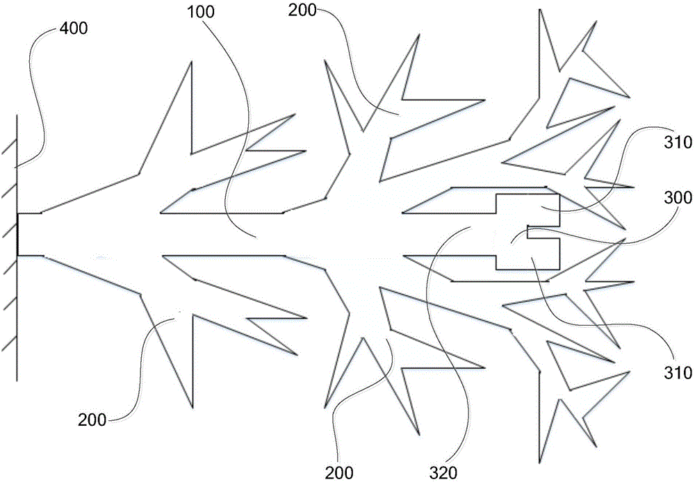
The present invention relates to a piezoelectric energy collector. The piezoelectric energy collector comprises piezoelectric plates which are used for generating a piezoelectric effect and comprise first piezoelectric plates and second piezoelectric plates, a multi-arm beam which comprises a main beam and a plurality of support beams arranged on the main beam, and a mass block, wherein one end of the main beam is fixedly arranged, the first piezoelectric plate is arranged on the main beam, the second piezoelectric plate is arranged on the support beams, the mass block is arranged at the other end of the main beam, and the mass block and the support beams are arranged in a staggered way. Through the setting of the main beam and the support beams, the main beam and the support beams have different vibration frequencies respectively, when vibration happens, the main beam and the support beams are matched with different vibration frequencies, thus the resonant frequency points of a whole system are increased, the frequency band is broadened, problems of a single working frequency and a narrow frequency band of a traditional piezoelectric energy collector are solved, the natural frequency of the main beam can be reduced through the setting of the mass block, thus the multi-arm beam and an environment vibration source reach a resonant state as soon as possible, generated voltage is larger, and the acquisition and conversion efficiency of the piezoelectric energy collector are improved.

Description

technical field [0001] The invention relates to the technical field of piezoelectric energy harvesting, in particular to a piezoelectric energy harvester and power generation equipment. Background technique [0002] Piezoelectric energy harvesting uses the piezoelectric effect of piezoelectric ceramic wafers to convert the vibration energy harvested in the working environment of wireless sensor network nodes into electrical energy. This technology solves the problem of self-supply power supply in a self-sufficient way, breaking through the new energy harvesting technology with short battery life and polluting the environment. Compared with other power generation principles, piezoelectric power generation has many advantages such as simple structure, no heat generation, no electromagnetic interference, no pollution, and easy realization of structure miniaturization and integration, and meets the functional requirements of low energy consumption products. [0003] The typical...

Claims


Application Information

Patent Timeline
IPC IPC(8): H02N2/18
CPCH02N2/186
Inventor 何雨睛叶涛
Owner SYSU CMU SHUNDE INT JOINT RES INST
Why Eureka
Eureka Blog
Learn More