
A constant-frequency equal-energy control method for a micro-spark pulse power supply

A technology of pulse power supply and control method, which is applied in the direction of circuits, manufacturing tools, electric processing equipment, etc., can solve the problems that the consistency of single discharge energy is difficult to guarantee, the breakdown time of the discharge gap is not fixed, and the breakdown delay time is different. Achieve a lot of signal logic processing capabilities, improve material removal rate, and drive speed

Active Publication Date: 2019-10-18
NANJING UNIV OF SCI & TECH
View PDF8 Cites 0 Cited by
  • Summary
  • Abstract
  • Description
  • Claims
  • Application Information

AI Technical Summary

Problems solved by technology

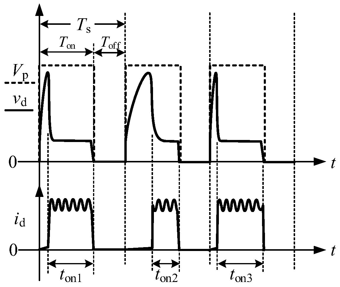
The former applies a pulse time T in the gap on and deionization time T off maintain a constant pulse voltage v p , its pulse voltage width and discharge frequency 1 / T s Fixed, similar to open-loop control, but due to the variable discharge gap in actual processing, the breakdown delay time is different, resulting in the real discharge time t on Not fixed, that is, the consistency of a single discharge energy is difficult to guarantee
The latter controls the discharge time T after the discharge gap breaks down on and deionization time T off Keep it fixed to realize the control of single discharge energy, and the discharge consistency is better, but this control strategy requires a detection circuit to identify the state of the discharge gap, and the breakdown time of the actual discharge gap is not fixed, so the actual discharge pulse v p The frequency of 1 / t s will keep changing

Method used

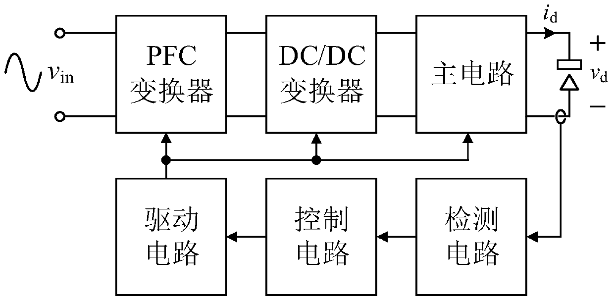
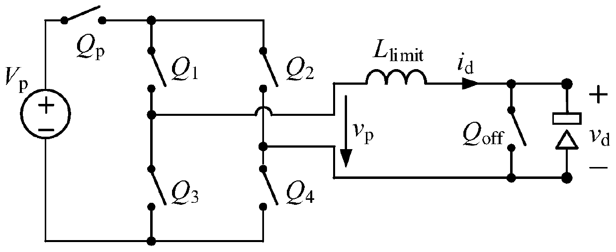

Image

  • A constant-frequency equal-energy control method for a micro-spark pulse power supply
  • A constant-frequency equal-energy control method for a micro-spark pulse power supply
  • A constant-frequency equal-energy control method for a micro-spark pulse power supply

Examples


Embodiment Construction

[0017] The solution of the present invention will be further described in detail below in conjunction with the accompanying drawings.

[0018] The energy control method such as the constant frequency of the micro-spark pulse power supply of the present invention is based on a high-speed hardware circuit. If the selected hardware bandwidth is too low, the response is too slow, and the delay is too long, this method cannot be realized. The following will first introduce Specific hardware circuit selection requirements.

[0019] In order to reduce the interference between the various parts of the EDM machine tool system, the general pulse power supply takes power from the AC input alone. Traditional pulse power supplies mostly use low-frequency transformers and bridge rectifiers plus capacitors for rectification. The power supply has a large volume and low input power factor. In order to reduce the influence of parasitic parameters on processing, reduce the size of the power sup...


PUM


Abstract

The invention discloses a constant-frequency equal-energy control method of a micro electric spark pulse power supply. According to a machining occasion and gap load characteristics, control parameters of the pulse power supply are set, and the pulse applying time and the deionizing time are determined; in the pulse applying stage, a gap voltage signal and a gap current signal are sampled, amplified correspondingly and summed, and closed-loop control is conducted on the sum result to enable the sum result to be consistent with a reference signal; after a gap is broken down, the current discharging stage is started, the corresponding breakdown time is recorded, the reference signal is updated according to the breakdown time, and closed-loop control is conducted on the sum result to enable the sum result to be consistent with the updated reference signal; and after current discharging, deionizing is conducted, and then the next machining period is conducted. According to the method, the sum of a gap voltage and a gap current is used as an only control variable for feeding back closed-loop control, and it is guaranteed that discharging energy is consistent every time while the voltage pulse frequency on the gap is kept constant.

Description

technical field [0001] The invention belongs to the field of high-frequency pulse power supply control for micro electric discharge machining, and in particular relates to a constant frequency and other energy control method of a micro electric discharge pulse power supply. Background technique [0002] EDM is a non-traditional machining technique that uses controlled electrical energy to form a spark discharge between an electrode and a tool to remove the material being machined. Existing pulse power supplies for EDM generally include non-independent pulse power supplies and independent pulse power supplies. The non-independent pulse power supply controls the maximum energy of a single discharge by adjusting the size of the discharge capacitor and the value of the charging voltage applied to it. When a small discharge capacitor and low charging voltage are used, the non-independent pulse power supply can provide extremely low discharge energy. It is still widely used in mi...

Claims


Application Information

Patent Timeline
Patent Type & Authority Patents(China)
IPC IPC(8): B23H1/02
Inventor 杨飞杨蛟华晗曹勇李春晖方斌
Owner NANJING UNIV OF SCI & TECH
Learn More