
Turnover coding machine for automobile part

A coding machine and automobile technology, applied in vehicle parts, manufacturing tools, transportation and packaging, etc., can solve the problems of unstable positioning, affecting the production line process, high price, etc., to save processing costs, improve work efficiency, and improve safety. sexual effect

Active Publication Date: 2017-09-22
大川精工(朝阳)有限公司
View PDF8 Cites 2 Cited by
  • Summary
  • Abstract
  • Description
  • Claims
  • Application Information

AI Technical Summary

Problems solved by technology

[0002] The laser coding machine gathers the laser on the surface of the marked object with a very high energy density, vaporizes the material on the surface, and then generates the text or pattern to be marked. During the working process of the traditional laser coding machine, Manually place the workpiece on the corresponding place of the laser coding machine, and manually remove the workpiece after the completion of the work. The labor cost is high, the price is expensive, and equipment failures often occur, which affects the production line process. In the process of use, it is often necessary to manually Positioning, the positioning is relatively unstable and it is easy to shake during the coding process. The pollution such as noise and smoke generated during the coding process will affect the health of the staff. In view of this situation, the present invention proposes a reversible Coding machine, through the improvement of existing equipment, can conveniently and quickly realize the loading and unloading of auto parts, and ensure the noise reduction and dust-free coding of processing during the coding process, which improves the safety of the staff next to it, and at the same time improves the The working efficiency of the staff is relatively stable when coding, it is not easy to slip and miss, the precision is high, and the structure is simple, which improves the work efficiency while saving the processing cost

Method used


Image

  • Turnover coding machine for automobile part
  • Turnover coding machine for automobile part
  • Turnover coding machine for automobile part

Examples


Embodiment Construction

[0029] It should be noted that, in the case of no conflict, the embodiments of the present invention and the features in the embodiments can be combined with each other.

[0030] In describing the present invention, it should be understood that the terms "center", "longitudinal", "transverse", "upper", "lower", "front", "rear", "left", "right", " The orientations or positional relationships indicated by "vertical", "horizontal", "top", "bottom", "inner" and "outer" are based on the orientations or positional relationships shown in the drawings, and are only for the convenience of describing the present invention and Simplified descriptions, rather than indicating or implying that the device or element referred to must have a particular orientation, be constructed and operate in a particular orientation, and thus should not be construed as limiting the invention. In addition, the terms "first", "second", etc. are used for descriptive purposes only, and should not be understood ...


PUM


Abstract

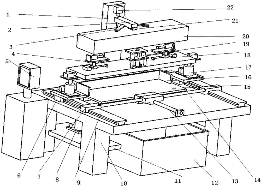
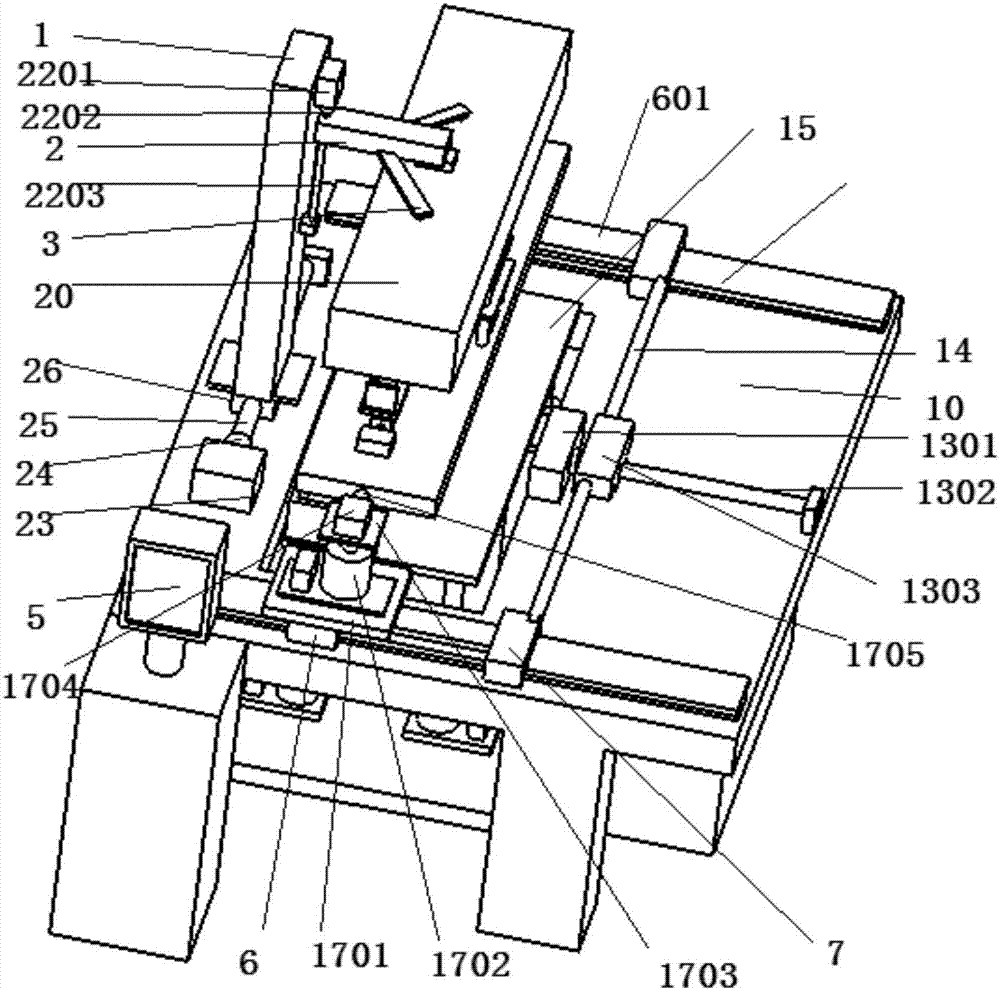
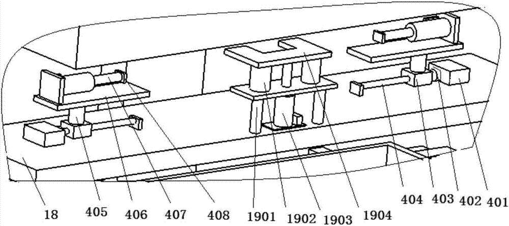
The invention provides a turnover coding machine for an automobile part. The turnover coding machine comprises a workbench. Supporting plates are arranged below the workbench. First air cylinders are arranged on the supporting plates. The top ends of the first air cylinders are jointly hinged to a bearing plate. Guide rails are distributed on the workbench. The other end of a square groove is in sliding connection with a fixed frame. A coding device is also in sliding connection to the fixed frame. The two guide rails are each provided with a first sliding block and a second sliding block. The two first sliding blocks are fixedly connected through a fixed rod. A third nut is arranged on the fixed rod. A coding stability increase device is arranged on each second sliding block through a lifting turnover mechanism. According to the turnover coding machine for the automobile part, the automobile part needing to be coded is fast clamped, alignment is fast and accurate, noise reduction dust-free coding of machining is guaranteed in the coding process, and meanwhile the automobile part is automatically discharged to a box; and in the whole process, the work efficiency is high, the good work environment of workers is guaranteed, and the safety of the workers is improved.

Description

technical field [0001] The invention belongs to the field of casting laser coding machines, in particular to a reversible coding machine for automobile parts. Background technique [0002] The laser coding machine gathers the laser on the surface of the marked object with a very high energy density, vaporizes the material on the surface, and then generates the text or pattern to be marked. During the working process of the traditional laser coding machine, Manually place the workpiece on the corresponding place of the laser coding machine, and manually remove the workpiece after the completion of the work. The labor cost is high, the price is expensive, and equipment failures often occur, which affects the production line process. In the process of use, it is often necessary to manually Positioning, the positioning is relatively unstable and it is easy to shake during the coding process. The pollution such as noise and smoke generated during the coding process will affect th...

Claims


Application Information

Patent Timeline
Patent Type & Authority Applications(China)
IPC IPC(8): B23K26/362B23K26/70
CPCB23K26/361B23K26/702B23K2101/006
Inventor 张海宽于大宽
Owner 大川精工(朝阳)有限公司
Learn More