
Weld neck flange machining technique

A technology of high neck flange and processing technology, which is applied in the direction of flange connection, pipe/pipe joint/pipe fitting, passing components, etc., which can solve the problems affecting the progress and development of product manufacturers, affecting the forming accuracy and consistency of products, and affecting the quality of products. Service life and other issues, to achieve the effect of easy control of neck forming quality, saving weld inspection costs and prolonging service life

Inactive Publication Date: 2017-09-22
JIANGYIN PUYANG FLANGE
View PDF8 Cites 3 Cited by
  • Summary
  • Abstract
  • Description
  • Claims
  • Application Information

AI Technical Summary

Problems solved by technology

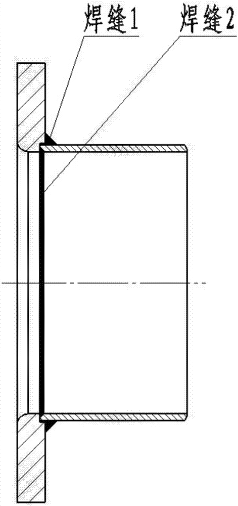
The high neck flange produced by this manufacturing method has the following main defects: 1. The welding area between the flange and the cylinder is prone to stress concentration, which reduces the fatigue strength of the product and affects the service life of the product; 2. During the welding process Medium-sized products are prone to deformation, which directly affects the forming accuracy and consistency of the product; 3. After the welding is completed, the internal surface welds of the product need to be fully polished, resulting in low production efficiency; 4. The full inspection of the product welds directly causes product failure. The cost of production has risen sharply
Due to the above reasons, if this processing method is used to process the high-neck flange of the high-voltage switch, it will greatly affect the progress and development of the product manufacturer.

Method used


Image

  • Weld neck flange machining technique
  • Weld neck flange machining technique

Examples


Embodiment 1

[0034] A high neck flange processing technology, the processing technology includes the following processing steps;

[0035] The first step: choose 8053 aluminum as raw material;

[0036] The second step: according to the specifications of the high-neck flange, select the specifications of the aluminum alloy cast rod, and ensure that the height-to-diameter ratio of the billet after blanking is ≤2.5;

[0037] Step 3: Aluminum alloy cast rods are turned and skinned to ensure that defects such as oxidation passivation layer, casting inclusions, subcutaneous air bubbles and other defects on the surface are removed.

[0038] The fourth step: forging the billet, put the peeled billet into the electric furnace for heating, and then forge to obtain the forged billet;

[0039] Step 5: Reaming, ring rolling the billet on a ring rolling mill to obtain a semi-finished product, wherein: the outer diameter of the neck and the outer diameter of the bottom of the semi-finished product reach ...

Embodiment 2

[0054] A high neck flange processing technology, the processing technology includes the following processing steps;

[0055] The first step: choose 8053 aluminum as raw material;

[0056] The second step: according to the specifications of the high-neck flange, select the specifications of the aluminum alloy cast rod, and ensure that the height-to-diameter ratio of the billet after blanking is ≤2.5;

[0057] Step 3: Aluminum alloy cast rods are turned and skinned to ensure that defects such as oxidation passivation layer, casting inclusions, subcutaneous air bubbles and other defects on the surface are removed.

[0058] The fourth step: forging the billet, put the peeled billet into the electric furnace for heating, and then forge to obtain the forged billet;

[0059] Step 5: Reaming, ring rolling the billet on a ring rolling mill to obtain a semi-finished product, wherein: the outer diameter of the neck and the outer diameter of the bottom of the semi-finished product reach ...

Embodiment 3

[0074] A high neck flange processing technology, the processing technology includes the following processing steps;

[0075] The first step: choose 8053 aluminum as raw material;

[0076] The second step: according to the specifications of the high-neck flange, select the specifications of the aluminum alloy cast rod, and ensure that the height-to-diameter ratio of the billet after blanking is ≤2.5;

[0077] Step 3: Aluminum alloy cast rods are turned and skinned to ensure that defects such as oxidation passivation layer, casting inclusions, subcutaneous air bubbles and other defects on the surface are removed.

[0078] The fourth step: forging the billet, put the peeled billet into the electric furnace for heating, and then forge to obtain the forged billet;

[0079] Step 5: Reaming, ring rolling the billet on a ring rolling mill to obtain a semi-finished product, wherein: the outer diameter of the neck and the outer diameter of the bottom of the semi-finished product reach ...


PUM

PropertyMeasurementUnit
tensile strengthaaaaaaaaaa
yield strengthaaaaaaaaaa

Abstract

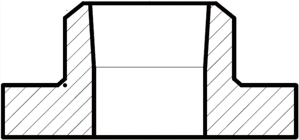
The invention discloses a high-neck flange processing technology, which includes the following processing steps: 8053 aluminum material is selected as the raw material, the aluminum alloy casting rod is turned and peeled, and forged to make a billet. The peeled billet is heated in an electric furnace, and then forged to obtain a forged billet. The billet is ring rolled on the ring rolling mill, the outer diameter of the semi-finished product neck and the outer diameter of the bottom reach the predetermined size, the inner diameter of the neck is smaller than the predetermined size, and the outer surface of the neck is straight, the height of the bottom and neck of the semi-finished product The height of the bottom and the neck of the blank is equal, the inner tapered surface of the neck is spun, the semi-finished product obtained after the hole expansion is installed in the spinning machine for spinning, and the roller of the spinning machine is lifted from the neck of the semi-finished product. The upper end of the neck starts to perform single-pass or multi-pass spinning on the inner surface of the neck from top to small, until the upper part of the inner surface of the semi-finished product is a bevel, and the outer diameter of the neck remains unchanged, and the inner diameter expands to a predetermined size , the height of the neck is increased to the predetermined size, and finally a high-neck flange that meets the requirements is obtained.

Description

technical field [0001] The invention relates to the technical field of flange processing machinery, in particular to a high neck flange processing technology. Background technique [0002] At present, the commonly used high-voltage switch high-neck flange is a split type, that is, the flange and the cylinder are processed separately, and then the flange and the cylinder are welded into one body by welding process, specifically as follows figure 1 shown. The high neck flange produced by this manufacturing method has the following main defects: 1. The welding area between the flange and the cylinder is prone to stress concentration, which reduces the fatigue strength of the product and affects the service life of the product; 2. During the welding process Medium-sized products are prone to deformation, which directly affects the forming accuracy and consistency of the product; 3. After the welding is completed, the internal surface welds of the product need to be fully polish...

Claims


Application Information

Patent Timeline
Patent Type & Authority Applications(China)
IPC IPC(8): B23P15/00F16L23/032
CPCB23P15/00F16L23/032
Inventor 秦雪忠
Owner JIANGYIN PUYANG FLANGE
Learn More