
Buried pipeline construction method

A construction method and technology of buried pipelines, which are applied in pipeline laying and maintenance, pipes/pipe joints/fittings, lifting equipment braking devices, etc., which can solve problems such as high mechanical shift costs, difficult operation, and short pipeline lengths , to achieve the effect of saving the cost of mechanical shifts, reducing the difficulty of operation, and easily grouping and constructing

Active Publication Date: 2017-09-22
CHINA 19TH METALLURGICAL CORP
View PDF5 Cites 15 Cited by
  • Summary
  • Abstract
  • Description
  • Claims
  • Application Information

AI Technical Summary

Problems solved by technology

[0003] 1. There are certain requirements for the site and space, and this method cannot be used for some construction sites that are difficult to reach by cranes;
[0004] 2. Although the operation of the crane is relatively flexible, its hoisting stability is poor, the operation error is large, safety accidents are prone to occur, and it is easy to cause certain damage to the pipeline;
[0005] 3. Due to the extremely difficult operation of double cranes, usually only a single crane can be used for operation. The length of the pipeline that can be hoisted by a single crane is short. However, it is very inconvenient to carry out these operations in the pipe trench, which greatly increases the labor intensity, and causes the efficiency of installing the pipeline to be very low;
[0006] 4. The mechanical shift fee of the crane is relatively high, which is not conducive to controlling the project cost

Method used


Image

  • Buried pipeline construction method
  • Buried pipeline construction method

Examples


Embodiment Construction

[0029] The present invention is further described below.

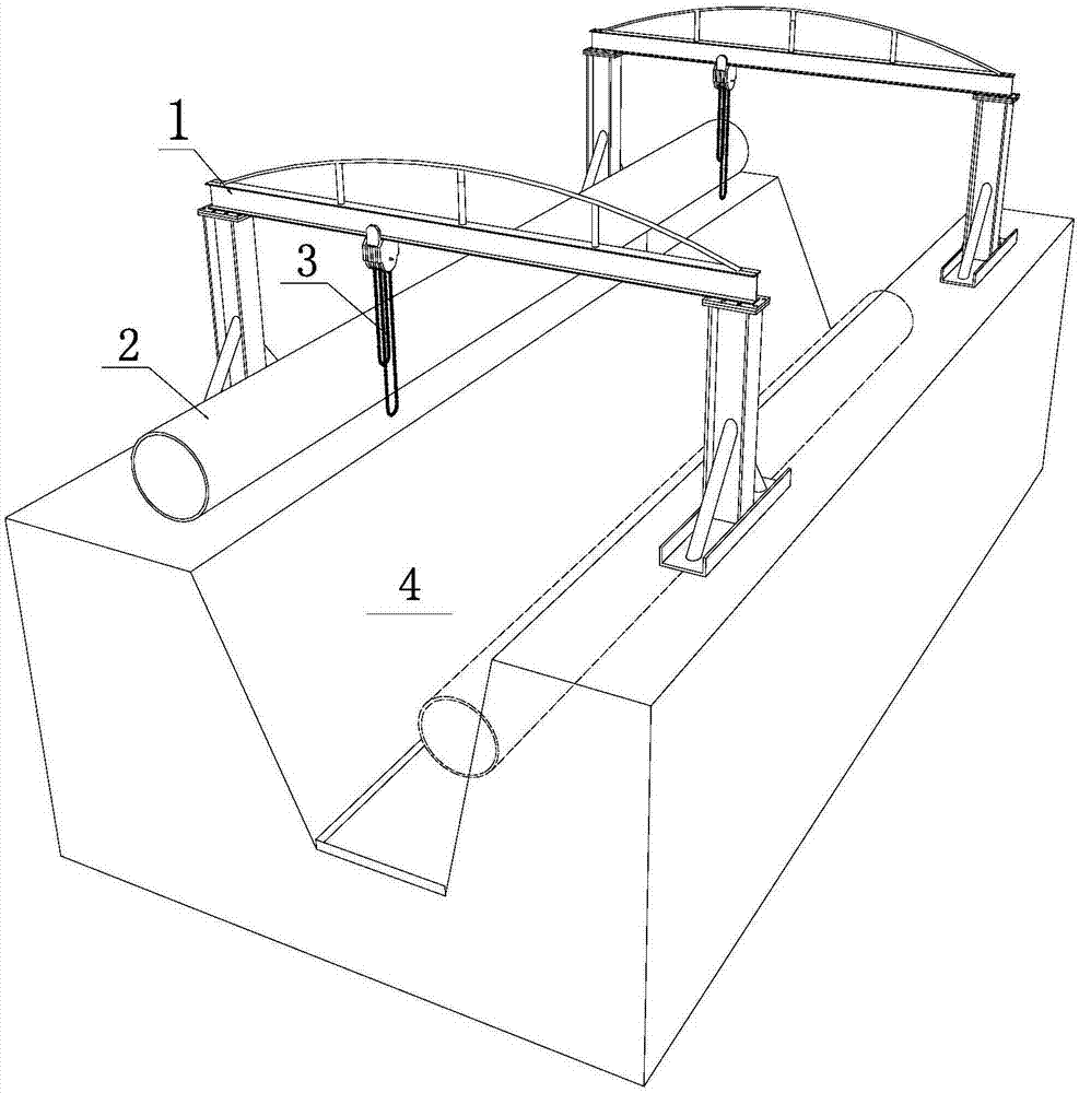
[0030] The buried pipeline construction method disclosed by the present invention comprises the following steps:

[0031] a. Excavate pipe trenches and transport materials in place;

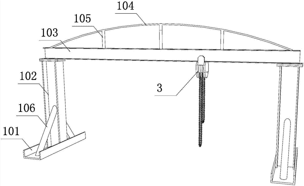
[0032] b. After the trench is excavated and the materials are in place, set up the trench pipeline transfer frame. The trench pipeline transfer frame includes at least two portal frames 1, and the portal frame 1 includes a base 101, a column 102, and a hoisting beam And upside down, the base 101 is set on both sides of the gantry 1, the column 102 is set on the base 101, the lifting beam 103 is set above the columns 102 on both sides, and the lifting beam 103 has a beam slide rail, the beam slide rail is provided with an inverted chain,

[0033] The gantry 1 is erected across and arranged above the pipe ditch, and a distance for placing the pipe 2 is reserved between a base 101 of the gantry 1 and the pipe ditch;

[0034] During constr...


PUM


Abstract

The invention relates to the field of pipeline construction and discloses a buried pipeline construction method. A pipe ditch pipeline transfer frame can be assembled on a construction site, the occupied area is small, site limitation is avoided, and construction can be carried out on a site where a large crane cannot arrive. At least two n-shaped frames are adopted for hoisting together, hoisting of long pipelines is facilitated, a space used for holding the pipelines is reserved between a base and a pipe ditch, thus splicing and corrosion resistant treatment of a very large part of pipelines can be conducted on the ground, operation difficulty is lowered to a large extent, construction efficiency can be improved, and a good protection effect can be achieved on finished pipelines. Compared with the prior crane hoisting mode, the buried pipeline construction method is good in hoisting stability and precision, easy assembly construction is ensured when the pipelines are put down to the ditch bottom, construction quality is greatly improved, and site construction can reduce mechanical machine-team cost and can also lower safety risk greatly.

Description

technical field [0001] The invention relates to the field of pipeline construction, in particular to a buried pipeline construction method. Background technique [0002] In municipal engineering, water conservancy engineering, building construction and metallurgical industry pipeline installation, construction operations of buried pipelines are often encountered. The existing trench pipeline construction method usually uses a large crane to hoist the pipeline in sections into the trench, and then assembles, welds and performs anti-corrosion treatment on the pipeline. The advantages of this construction method are flexible construction and fast hoisting, but it also has many defects: [0003] 1. There are certain requirements for the site and space, and this method cannot be used for some construction sites that are difficult to reach by cranes; [0004] 2. Although the operation of the crane is relatively flexible, its hoisting stability is poor, the operation error is lar...

Claims


Application Information

Patent Timeline
IPC IPC(8): F16L1/036F16L1/06B66C5/04
CPCB66C5/04F16L1/036F16L1/06
Inventor 张超
Owner CHINA 19TH METALLURGICAL CORP
Learn More