
Sand blasting head position adjusting device based on position detection and sand blasting device

A technology of detection device and sandblasting device is applied in used abrasive processing devices, explosion generating devices, spray guns and other directions, which can solve the problems of environmental pollution, affecting the safety of on-site operators and the consumption of steel grit, and achieve good safety, Sandblasting quality with high reliability and high reliability effects

Pending Publication Date: 2017-09-26
四川邦立重机有限责任公司
View PDF8 Cites 4 Cited by
  • Summary
  • Abstract
  • Description
  • Claims
  • Application Information

AI Technical Summary

Problems solved by technology

[0003] Aiming at the above-mentioned problems that the steel grit cannot be completely recovered due to the change of the distance between the nozzle and the surface of the pipeline, the steel grit splashes and sand leaks, which affects the safety of on-site operators and the excessive consumption of steel grit, and causes environmental pollution. The present invention provides a A sandblasting head position adjustment device and a sandblasting device based on position detection. The position adjustment device has a simple structure and can effectively control the distance between the sandblasting head and the pipeline surface, thereby ensuring the safety of on-site operators and reducing steel grit consumption speed and environmental protection; the sandblasting device has high reliability of sandblasting quality, good safety, slow consumption of steel grit, and environmental protection

Method used


Image

  • Sand blasting head position adjusting device based on position detection and sand blasting device
  • Sand blasting head position adjusting device based on position detection and sand blasting device

Examples


Embodiment 1

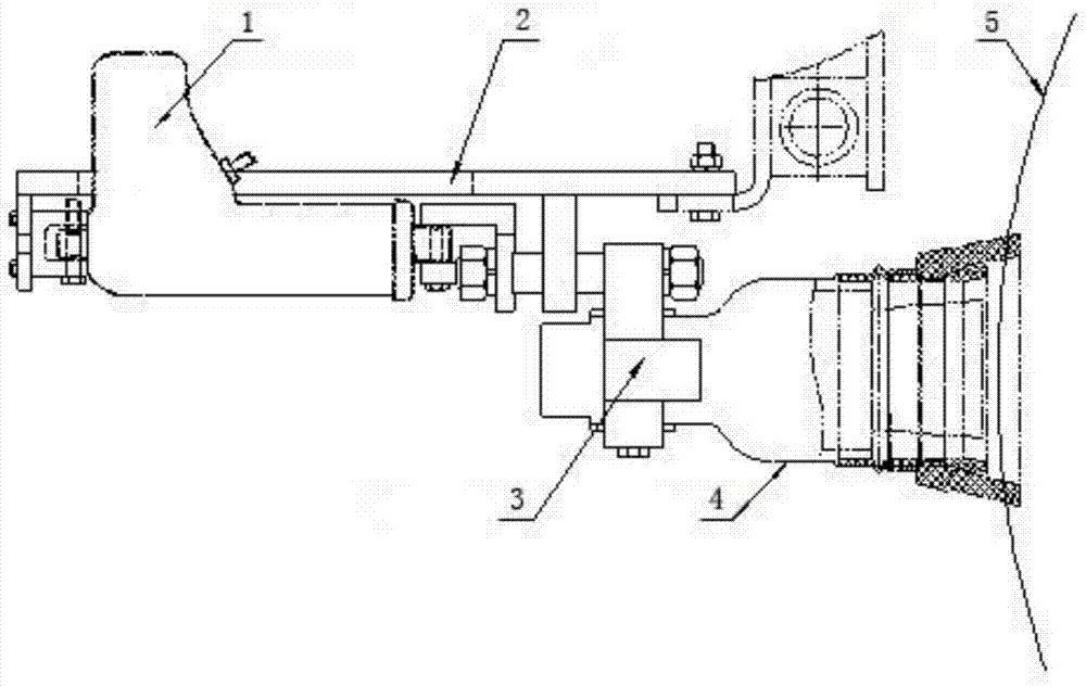
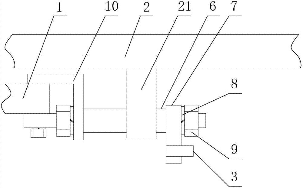
[0032] Such as figure 1 with figure 2 As shown, a position adjustment device for a sandblasting head based on position detection includes a mounting plate 7 for fixing the sandblasting head 4, and also includes a position detection device 3 and a driving mechanism 1. The mounting plate 7 is mounted on the driving mechanism 1 Above, the driving mechanism 1 is used to adjust the position of the mounting plate 7;

[0033] The position detection device 3 is used to detect the relative position of the sandblasting head 4 or the mounting plate 7 and the workpiece 5, and the signal output end of the position detection device 3 is connected to the control unit of the driving mechanism 1, and the output signal of the position detection device 3 is used as The control signal for the operation of the drive mechanism 1.

[0034] The above adjustment device has a simple structure. The drive mechanism 1 is used to install on the frame 2 matched with the sandblasting device. At the same time, t...

Embodiment 2

[0038] Such as figure 1 with figure 2 As shown, this embodiment is further limited on the basis of Embodiment 1: As an integrated solution, the position detection device 3 is fixed on the mounting plate 7. As a person skilled in the art, if the position detecting device 3 is to realize its function, it can move with the sandblasting head 4, so the position detecting device 3 can also be installed on the sandblasting head 4.

[0039] As a specific solution that is easy to implement, the position detection device 3 is a distance measuring sensor, and the driving mechanism 1 is a linear motor that outputs linear motion. In this solution, the distance measuring sensor can be a commonly used sensor based on laser, infrared, ultrasonic and other measurement methods. The specific selection of the driving mechanism 1 is to make the device as small in size and light in weight as possible. , To better adapt to field work. As a person skilled in the art, the above driving mechanism 1 can...

Embodiment 3

[0041] This embodiment further limits the case on the basis of the technical solution provided in embodiment 1, such as figure 1 with figure 2 As shown, this embodiment provides a sandblasting device based on position detection, which includes a sandblasting head 4 and a frame 2, and also includes any one of the sandblasting head 4 position adjustment devices provided in any of the above embodiments. The mechanism 1 is fixed on the frame 2, and the sandblasting head 4 is fixed on the mounting plate 7;

[0042] The movement direction of the mounting plate 7 under the action of the driving mechanism 1 is parallel to the direction of the sandblasting port of the sandblasting head 4. In the above sandblasting device, the distance between the sandblasting head 4 and the pipe surface can be effectively controlled, so as to ensure the safety of on-site operators, reduce the speed of steel grit consumption, and be environmentally friendly; at the same time, because the nozzles of the sa...


PUM


Abstract

The invention discloses a sand blasting head position adjusting device based on position detection and a sand blasting device. The adjusting device comprises an installing plate used for fixing a sand blasting head and further comprises a position detecting device and a drive mechanism. The installing plate is installed on the drive mechanism. The drive mechanism is used for adjusting the position of the installing plate. The position detecting device is used for detecting the relative position between the sand blasting head or the installing plate and a workpiece. The signal output end of the position detecting device is connected with a control unit of the drive mechanism. An output signal of the position detecting device serves as a control signal of work of the drive mechanism. The sand blasting device comprises the sand blasting head, a rack and the adjusting device. The position adjusting device is simple in structure, the distance between the sand blasting head and the surface of a pipeline can be effectively controlled, and therefore the effects of guaranteeing safety of site operators, reducing steel grit consumption speed and being beneficial to environmental protection are achieved. The sand blasting device is high in sand blasting quality reliability, meanwhile, safety is good, the steel grit consumption speed is low, and the position adjusting device is environmentally friendly.

Description

Technical field [0001] The present invention relates to the technical field of metal material surface treatment equipment, in particular to a sandblasting head position adjustment device and a sandblasting device based on position detection. Background technique [0002] During the construction of the oil pipeline, the joints of the pipeline are welded and stored in the open air. The joints need to be sandblasted before the protective treatment is implemented. In the automatic sandblasting device with recovery system currently used, the nozzle is in When the pipe surface is moving, the distance between the nozzle and the pipe surface will change due to the different force directions of the nozzle and the unevenness of the pipe surface. When the distance is too large or too small, the steel grit cannot be fully recovered, causing steel grit to splash and leak. On-site operator safety and rapid consumption of steel grit have caused environmental pollution. Summary of the invention...

Claims


Application Information

Patent Timeline
IPC IPC(8): B24C1/00B24C5/04B24C9/00
CPCB24C1/00B24C5/04B24C9/00
Inventor 钟春健彭俊红李昌武郑常敏
Owner 四川邦立重机有限责任公司
Learn More