Compound multifunctional shot blasting machine

A multi-functional, shot blasting machine technology, applied in abrasive jet machine tools, used abrasive treatment devices, filter screens, etc., can solve the problems of single function, low work efficiency, and low resource utilization, and achieve resource utilization. High, high work efficiency, and the effect of improving the processing effect

Pending Publication Date: 2017-09-26
JIANGXI UNIV OF SCI & TECH
View PDF9 Cites 5 Cited by
  • Summary
  • Abstract
  • Description
  • Claims
  • Application Information

AI Technical Summary

Problems solved by technology

[0006] In order to overcome the shortcomings of single function, low work efficiency and low resource utilization rate of the shot blasting machine in the prior art, the technical problem to be solved by the present invention is to provide a machine that can process large and small workpieces alone, and can process large and small workpieces at the same time. , small workpieces, and a compound multi-functional shot blasting machine with high work efficiency and high resource utilization

Method used


Image

  • Compound multifunctional shot blasting machine
  • Compound multifunctional shot blasting machine
  • Compound multifunctional shot blasting machine

Examples


Embodiment 1

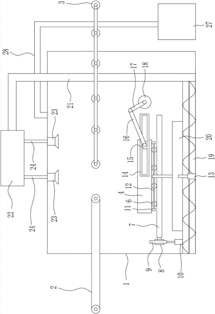
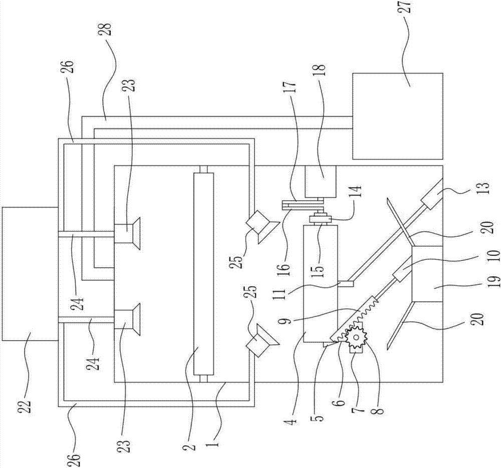
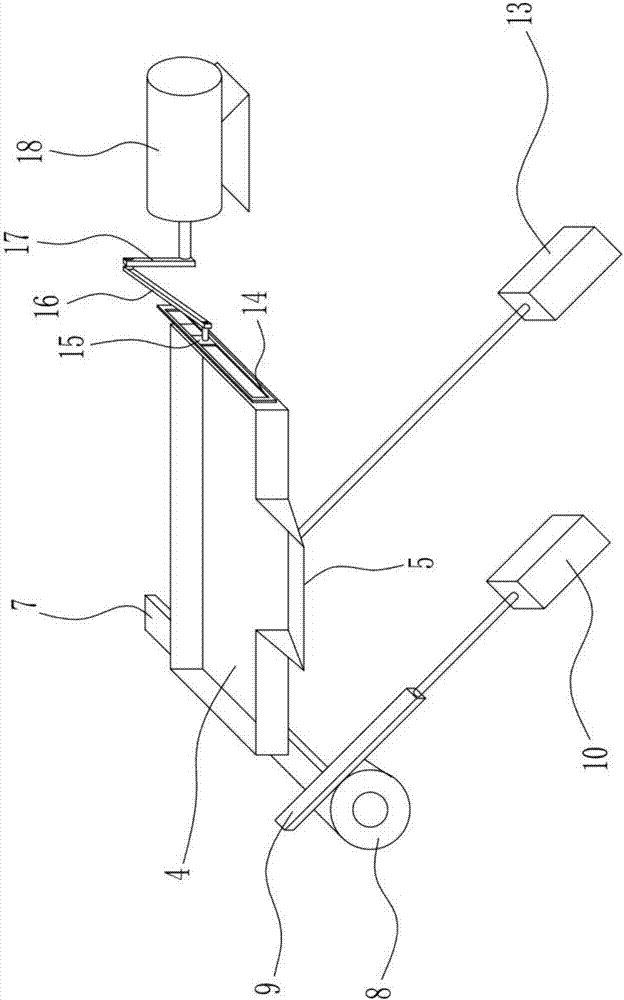
[0036] A compound multifunctional shot blasting machine, such as Figure 1-Figure 6 As shown, it includes frame 1, conveying device 2, roller table 3, screw conveyor 19, baffle plate 20, bucket elevator 21, separator 22, shot blaster I23, feeding pipe I24, shot blaster II25 , feeding pipe II 26, dust remover 27 and dust suction cylinder 28, a transmission device 2 is installed on the frame 1, a roller table 3 is installed on the right side of the transmission device 2, and a screw conveyor 19 is installed below the roller table 3, and the screw conveyor Baffles 20 are welded symmetrically on both sides of 19, a bucket elevator 21 is connected to the right end of the screw conveyor 19, and a separator 22 is connected to the other end of the bucket elevator 21, and the separator 22 is fixedly installed on the upper side of the frame 1 to separate There are eight shot blasting devices I23 fixedly installed under the device 22, and a feeding pipe I24 is connected between the shot ...

Embodiment 2

[0038] A compound multifunctional shot blasting machine, such as Figure 1-Figure 8 As shown, it includes frame 1, conveying device 2, roller table 3, screw conveyor 19, baffle plate 20, bucket elevator 21, separator 22, shot blaster I23, feeding pipe I24, shot blaster II25 , feeding pipe II 26, dust remover 27 and dust suction cylinder 28, a transmission device 2 is installed on the frame 1, a roller table 3 is installed on the right side of the transmission device 2, and a screw conveyor 19 is installed below the roller table 3, and the screw conveyor Baffles 20 are welded symmetrically on both sides of 19, a bucket elevator 21 is connected to the right end of the screw conveyor 19, and a separator 22 is connected to the other end of the bucket elevator 21, and the separator 22 is fixedly installed on the upper side of the frame 1 to separate There are eight shot blasting devices I23 fixedly installed under the device 22, and a feeding pipe I24 is connected between the shot ...


PUM


Abstract

The invention relates to a shot blasting machine, and particularly to a compound multifunctional shot blasting machine. The invention aims to solve the technical problem of providing the compound multifunctional shot blasting machine which has the benefits as follows: large and small workpieces can be treated either independently or simultaneously, the working efficiency is high, and the resource utilization rate is high. In order to solve the technical problem, the compound multifunctional shot blasting machine provided by the invention comprises a vibrating screen, guide wheels, a turnover plate, a gear, a toothed rack, a hydraulic cylinder I and the like; the guide wheels are rotatably mounted on the rear side of the vibrating screen; the turnover plate is rotatably mounted below the guide wheels; the gear is fixedly connected with the left end of the turnover plate; the hydraulic cylinder I is fixedly mounted below the gear; the toothed rack is fixedly connected with the output end of the hydraulic cylinder I; and the gear is meshed with the toothed rack. According to the compound multifunctional shot blasting machine, the effects that both large and small workpieces can be treated either independently or simultaneously, the working efficiency is high, and the resource utilization rate is high.

Description

technical field [0001] The invention relates to a shot blasting machine, in particular to a composite multifunctional shot blasting machine. Background technique [0002] Shot blasting machine refers to casting equipment that uses high-speed projectiles thrown by a shot blaster to clean or strengthen the surface of castings. Shot blasting technology is mainly used for derusting, descaling and surface quality enhancement of castings on metal surfaces. The surface of the material can be cleaned circularly by shot blasting, the structure of the surface of the material can be modified, and a chilled layer and surface residual stress can be generated on the plastic surface, which can further improve the bearing capacity of the material and prolong the service life of the parts. The shot blasting process uses the high-speed movement of the shot blasting wheel, and under the action of gravity and centrifugal force, the shot is thrown and impacted on the surface of the workpiece at...

Claims


Application Information

Patent Timeline
Patent Type & Authority Applications(China)
IPC IPC(8): B24C1/08B24C3/04B24C3/08B24C3/14B24C9/00B07B1/30B07B1/42
CPCB07B1/30B07B1/42B24C1/086B24C3/04B24C3/083B24C3/14B24C9/00B24C9/003B24C9/006
Inventor 刘赣华刘军刘洪林
Owner JIANGXI UNIV OF SCI & TECH
Why Eureka
Try Eureka