Rolling centrifugal driving device

A driving device, centrifugal technology, applied in the direction of engine components, machines/engines, hydroelectric power generation, etc., can solve the problems of short service life, reduced loading, and various equipment

Inactive Publication Date: 2017-09-26
刘运武
View PDF0 Cites 0 Cited by
  • Summary
  • Abstract
  • Description
  • Claims
  • Application Information

AI Technical Summary

Problems solved by technology

The most common ones are water power, fire power and wind power. The disadvantage is that although the operating cost of hydropower in nature is low, the construction of hydropower stations is restricted by many conditions. First, there must be a certain flow difference and flow rate. It is necessary to build dams and ship locks to raise the water level, and it is a waste of time for large and small ships to pass through the ship locks; after the water level is raised, it will inevitably flood fields, houses and forests, etc., so many people need to be resettled when building hydropower stations; The flow varies widely from time to time, which affects power generation; in addition, the construction of hydropower stations requires a lot of investment and takes a long time; wind power and solar energy depend on the weather and are subject to nature
[0004] Thermal power plants are the most common in the world today, that is, they provide the most electricity for human beings. The principle of power generation is to use the combustion of fuel to heat water into steam, and the high-temperature and high-pressure water vapor drives the turbine to rotate to convert thermal energy (chemical energy) into mechanical energy. , and then the steam turbine drives the generator to convert mechanical energy into electrical energy during operation, so it not only wastes a lot of limited resources such as coal, but also brings pollution to the environment
In addition, the production process of thermal power plants requires a large number of equipment and complex structures. As long as there is a problem in one of the links, it will affect the overall situation.
Since electricity cannot be st...

Method used


Image

  • Rolling centrifugal driving device
  • Rolling centrifugal driving device
  • Rolling centrifugal driving device

Examples


Embodiment Construction

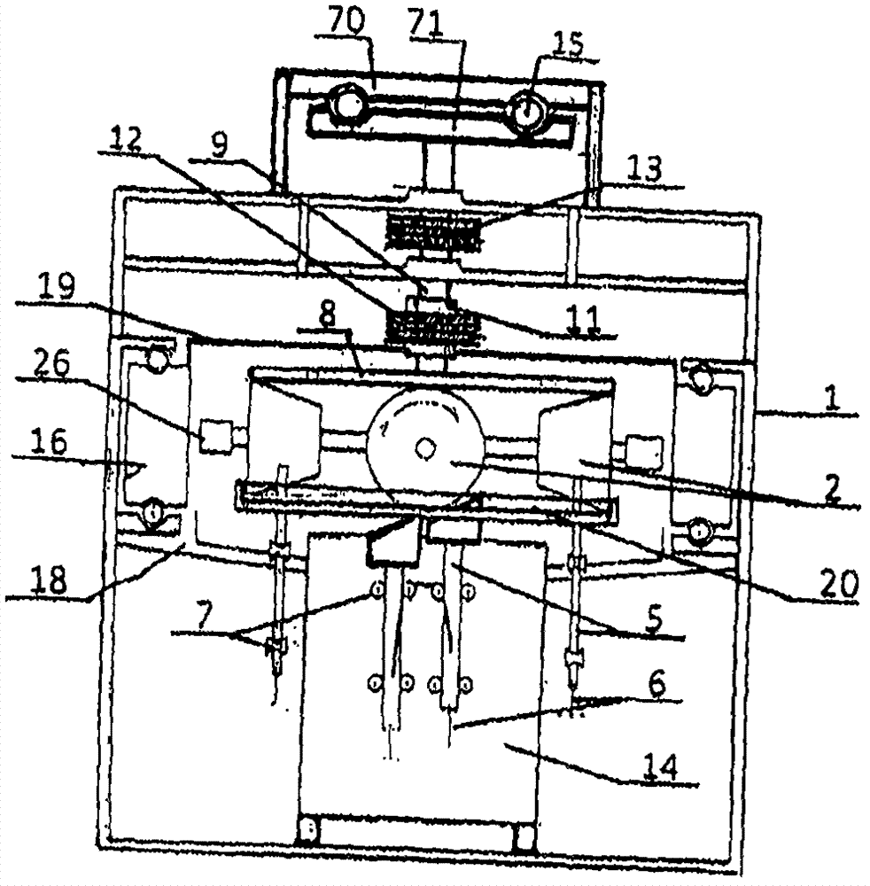
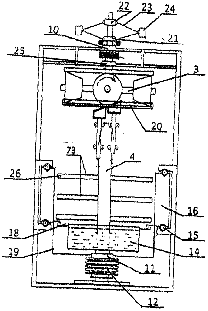
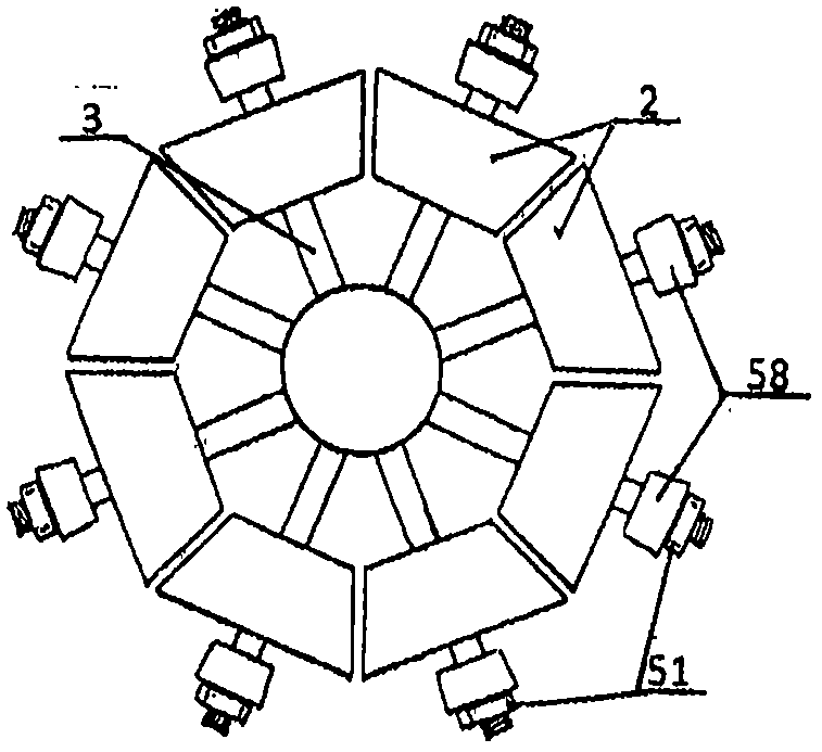
[0047] Further clarification will be made below in conjunction with the accompanying drawings.

[0048] refer to Figure 1 to Figure 3, a plurality of rollers 2 (only three in the left and right are shown in the figure) arranged in an annular ring are placed on the annular track 20, each roller is connected by a central drive shaft 3 and each roller is connected as a whole, the pressure plate 8 The outer edge circumference of the lower plane is pressed against the top dead center of each roller 2, and the vertical shaft 9 is installed in the middle of the upper plane of the pressure plate 8. The vertical shaft is supported and positioned by the upper and lower bearing seats 10 and 25 respectively containing bearings. The top of the upper end of 9 is equipped with a moving plate 71 that can run with the vertical shaft, and the upper section of the vertical shaft is equipped with a transmission wheel 13 for receiving the transmission of the power (not shown in the figure) machin...


PUM


Abstract

The invention discloses a rolling centrifugal driving device, which aims to provide a simple structure, no resource consumption and no environmental pollution, which can be used for power generation, and can also be used for driving various machines and driving vehicles. The main points of the technical scheme are: the rolling and rotating rollers or the pressure rollers installed on the exposed roller center transmission shaft are in operation and the inclined blades are in operation to promote the contact with the lower side. The pull rod for in-situ lifting is used to lift up and down; a suction pipe is installed at the lower part of the central intersection of several rollers or blades arranged in a ring. The circumference is connected with the output pipes, and the jet outlet is located on the outer edge of the annular pipe connected with each output pipe. The centrifugal force formed during operation promotes the high-speed jet to drive the impeller to rotate. Work is done by driving the machine when the pull rod is up and down and the impeller is rotating.

Description

technical field [0001] The present invention relates to a power part used to drive a machine to run, more precisely and more specifically, the working part of the machine is driven to run to perform work by means of the power generated by the device during operation. Background technique [0002] As we all know, machines are driven by power during operation. The power includes electric motors, internal combustion engines, and water power and wind power in nature. Whether it is deceleration or deceleration, there is inevitably a certain resistance, which must consume a certain amount of energy as a price. For example, pumping water to store energy for power generation, pumping water with one kilowatt of electric energy, and releasing water can only generate 0.75 kilowatts of electricity at most, that is, lost a quarter. [0003] Power plants around the world today include water power, thermal power, wind power, geothermal power, solar energy, atomic energy, that is, nuclear ...

Claims


Application Information

Patent Timeline
IPC IPC(8): F03B17/00
CPCY02E10/20F03B17/00
Inventor 刘运武
Owner 刘运武
Why Eureka
Try Eureka