New type dewatering device used for rare earth carbonate

A dehydration device and rare earth carbonate technology, applied in non-progressive dryers, drying solid materials, dryers, etc., can solve the problems of difficult maintenance, numerous structures, complex parts, etc., to achieve good dehydration effect and improve dehydration efficiency. Effect

Active Publication Date: 2017-09-26
威海博思医疗科技有限公司 +1
View PDF6 Cites 6 Cited by
  • Summary
  • Abstract
  • Description
  • Claims
  • Application Information

AI Technical Summary

Problems solved by technology

[0005] In order to overcome the disadvantages that the existing dehydration device for rare earth carbonate generally adopts a traditional structure, the parts used are numerous and complex in structure, and difficult to maintain and repair, the technical problem to be solved by the present invention is to provide a dehydration device for rare earth carbonate New dehydration device

Method used


Image

  • New type dewatering device used for rare earth carbonate
  • New type dewatering device used for rare earth carbonate
  • New type dewatering device used for rare earth carbonate

Examples


Embodiment 1

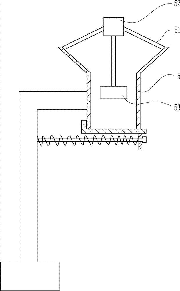
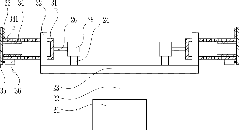
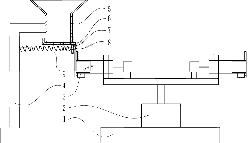
[0028] A new type of dehydration device for rare earth carbonate, such as Figure 1-4 As shown, it includes a base 1, a rotating device 2, a dehydrating device 3, an L-shaped bracket 4, a hopper 5, an L-shaped baffle 6, a slide plate 7, a T-shaped guide rod 8 and a spring 9; The rotating device 2 is provided with a dehydrating device 3 above the rotating device 2, and the dehydrating device 3 is left-right symmetrically arranged, and an L-shaped bracket 4 is arranged on the left side of the dehydrating device 3, and the upper right end of the L-shaped bracket 4 is connected to the feeding hopper 5 The left side wall of the hopper is connected by welding, an L-shaped baffle 6 is arranged below the hopper 5, and a discharge port is provided at the bottom of the hopper 5, and the L-shaped baffle 6 connects the discharge port at the bottom of the hopper 5 Block, the L-shaped baffle 6 and the hopper 5 are set to be flexibly connected, the right end of the bottom of the L-shaped baf...

Embodiment 2

[0030] A new type of dehydration device for rare earth carbonate, such as Figure 1-4 As shown, it includes a base 1, a rotating device 2, a dehydrating device 3, an L-shaped bracket 4, a hopper 5, an L-shaped baffle 6, a slide plate 7, a T-shaped guide rod 8 and a spring 9; The rotating device 2 is provided with a dehydrating device 3 above the rotating device 2, and the dehydrating device 3 is left-right symmetrically arranged, and an L-shaped bracket 4 is arranged on the left side of the dehydrating device 3, and the upper right end of the L-shaped bracket 4 is connected to the feeding hopper 5 The left side wall of the hopper is connected by welding, an L-shaped baffle 6 is arranged below the hopper 5, and a discharge port is provided at the bottom of the hopper 5, and the L-shaped baffle 6 connects the discharge port at the bottom of the hopper 5 Block, the L-shaped baffle 6 and the hopper 5 are set to be flexibly connected, the right end of the bottom of the L-shaped baf...

Embodiment 3

[0033] A new type of dehydration device for rare earth carbonate, such as Figure 1-4 As shown, it includes a base 1, a rotating device 2, a dehydrating device 3, an L-shaped bracket 4, a hopper 5, an L-shaped baffle 6, a slide plate 7, a T-shaped guide rod 8 and a spring 9; The rotating device 2 is provided with a dehydrating device 3 above the rotating device 2, and the dehydrating device 3 is left-right symmetrically arranged, and an L-shaped bracket 4 is arranged on the left side of the dehydrating device 3, and the upper right end of the L-shaped bracket 4 is connected to the feeding hopper 5 The left side wall of the hopper is connected by welding, an L-shaped baffle 6 is arranged below the hopper 5, and a discharge port is provided at the bottom of the hopper 5, and the L-shaped baffle 6 connects the discharge port at the bottom of the hopper 5 Block, the L-shaped baffle 6 and the hopper 5 are set to be flexibly connected, the right end of the bottom of the L-shaped baf...


PUM


Abstract

The invention relates to a dewatering device, in particular to a new type dewatering device used for rare earth carbonate. According to the technical purpose, the new type dewatering device used for the rare earth carbonate is provided. In order to achieve the technical purpose, the new type dewatering device used for the rare earth carbonate is provided, and comprises a base, a rotating device, a dewatering device body, an L-shaped support, a feeding hopper, an L-shaped baffle and the like; the dewatering device body is arranged above the rotating device, and is arranged in a left-right symmetry manner; the L-shaped support is arranged on the left side of the dewatering device body; the upper right end of the L-shaped support is connected with the left side wall of the feeding hopper in a welded manner; and the L-shaped baffle is arranged below the feeding hopper. According to the new type dewatering device used for the rare earth carbonate, by means of combination of the rotating device and the dewatering device body, the rare earth carbonate can be conveniently dewatered, and the split type structure is adopted.

Description

technical field [0001] The invention relates to a dehydration device, in particular to a novel dehydration device for rare earth carbonate. Background technique [0002] Rare earths are known as "industrial vitamins". Now it has become an extremely important strategic resource. Rare earth element oxides refer to oxides of 15 lanthanide elements with atomic numbers from 57 to 71 in the periodic table of elements, and oxides of scandium and yttrium, a total of 17 elements whose chemical properties are similar to lanthanide elements. Rare earth elements have been widely used in petroleum, chemical industry, metallurgy, textile, ceramics, glass, permanent magnet materials and other fields. With the advancement of science and technology and continuous breakthroughs in application technology, the value of rare earth oxides will increase. Adding rare earth metals or fluorides and silicides to steel can play the role of refining, desulfurization, neutralizing harmful impurities wi...

Claims


Application Information

Patent Timeline
Patent Type & Authority Applications(China)
IPC IPC(8): F26B11/18F26B25/00
CPCF26B11/181F26B25/00F26B25/002
Inventor 不公告发明人
Owner 威海博思医疗科技有限公司
Why Eureka
Try Eureka