Cylinder sleeve for oil exploitation and preparation method of cylinder sleeve

A technology for oil extraction and cylinder liner, applied in the direction of cylinders, mechanical equipment, components of pumping devices for elastic fluids, etc., can solve the problems of wear resistance, corrosion resistance and fatigue resistance characteristics Potential safety hazards, insufficient uniformity of cylinder liner texture, etc., to achieve the effect of improving mechanical performance, ensuring safety, and enhancing strength

Inactive Publication Date: 2017-09-29
成都金信元机械设备有限公司
View PDF9 Cites 9 Cited by
  • Summary
  • Abstract
  • Description
  • Claims
  • Application Information

AI Technical Summary

Problems solved by technology

With this structure of the cylinder liner, the fitting end of the cylinder liner is likely to come into contact with the fittings or other hard objects during the installation process, causing the cylinder liner to be bumped. The small contact surface of the inner and outer sleeves leads to the danger of the inner sleeve falling off, which poses a great hidden danger to the operating efficiency of the equipment and the safety of personnel
[0003] In recent years, when drilling under complex geological conditions such as deep wells, hard rock formations, and ocean drilling, the jet drilling technology under the conditions of high pump pressure and large displacement has been vigorously promoted. Fatigue characteristics put forward higher requirements. Traditional cylinder liners can no longer meet the requirements of use, and cylinder liners are prone to early failure, resulting in high drilling costs. The main reasons are insufficient wear resistance, corrosion resistance and fatigue resistance. At the same time, The texture of the cylinder liner is not uniform enough, and there are gaps in the material, which also affects its strength

Method used


Image

  • Cylinder sleeve for oil exploitation and preparation method of cylinder sleeve
  • Cylinder sleeve for oil exploitation and preparation method of cylinder sleeve
  • Cylinder sleeve for oil exploitation and preparation method of cylinder sleeve

Examples


Embodiment

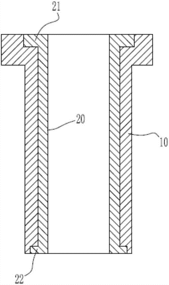
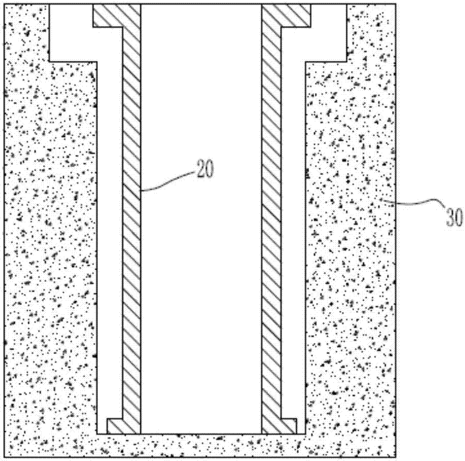
[0043] Such as Figure 2-4As shown, a cylinder liner for oil development includes an outer sleeve 10 and an inner sleeve 20; the inner sleeve 20 is embedded in the outer sleeve 10; the two ends of the inner sleeve 20 are respectively provided with a first ring sleeve 21 and a second The two rings 22, the first ring 21 and the second ring 22 are integrally formed with the inner sleeve 20; the two ends of the outer sleeve 10 are respectively provided with a first ring groove and a second ring groove. The first ring sleeve 21 is located in the first ring groove, and the second ring sleeve 22 is located in the second ring groove.

[0044] By setting the first ring sleeve 21 and the second ring sleeve 22 on the inner sleeve 20, the outer sleeve 10 is provided with a first ring groove and a second ring groove respectively matched with the first ring sleeve 21 and the second ring sleeve 22, Clamping the inner sleeve 21 in the outer sleeve 10 completely avoids the risk of the traditi...


PUM

PropertyMeasurementUnit
thicknessaaaaaaaaaa
particle diameteraaaaaaaaaa

Abstract

The invention discloses a cylinder sleeve for oil exploitation. The cylinder sleeve comprises an outer sleeve and an inner sleeve. The inner sleeve is nested in the outer sleeve. The two ends of the inner sleeve are provided with a first annular sleeve and a second annular sleeve correspondingly. The first annular sleeve, the second annular sleeve and the inner sleeve are of an integrally formed integrated structure. The two ends of the outer sleeve are provided with a first annular groove and a second annular groove correspondingly. The first annular sleeve is located in the first annular groove. The second annular sleeve is located in the second annular groove. The invention further discloses a preparation method of the cylinder sleeve for oil exploitation. A traditional cylinder sleeve is improved in three respects of structure, material and preparation process, the effect that sleeve falling of the outer sleeve does not occur can be ensured through the improvement in structure, abrasion resistance, corrosion resistance and fatigue resistance of the cylinder sleeve are promoted greatly through the improvements in material and preparation process, and the produced cylinder sleeve is uniform in texture and high in strength.

Description

technical field [0001] The invention belongs to the technical field of petroleum exploitation, and in particular relates to a cylinder liner for petroleum exploitation and a preparation method thereof. Background technique [0002] The cylinder liner of the oil drilling mud pump is a key component. One end of the cylinder liner is assembled with the mud pump cylinder assembly. The piston rod at the power end is connected to the piston to perform high-pressure axial reciprocating motion inside the cylinder liner to realize the drilling mud. suction and discharge. The traditional cylinder liner is mainly composed of a cylinder inner liner and a cylinder outer liner, such as figure 1 As shown, the axial lengths of the inner cylinder a and the outer cylinder b are consistent, and in the assembled state, the two ends of the inner cylinder a are flush with the two ends of the outer cylinder b. With this structure of the cylinder liner, the fitting end of the cylinder liner is li...

Claims


Application Information

Patent Timeline
Patent Type & Authority Applications(China)
IPC IPC(8): F04B53/16C22C38/56C22C38/02C22C38/04C22C38/44C22C38/46C22C38/06C22C38/60B22D19/00C21D1/26C21D1/18C23C8/66C04B35/584C04B35/622
CPCB22D19/0009C04B35/584C04B35/622C04B2235/3206C04B2235/3217C04B2235/3272C04B2235/3826C04B2235/445C21D1/18C21D1/26C22C38/005C22C38/02C22C38/04C22C38/06C22C38/44C22C38/46C22C38/56C22C38/60C23C8/66F04B53/166
Inventor 廖君
Owner 成都金信元机械设备有限公司
Why Eureka
Try Eureka