
Line structured light visual sensor calibration method based on sawtooth target

A technology of visual sensor and calibration method, which is applied in the field of sensor calibration, and can solve the problems of unable to capture target feature point images, difficult to clear images, difficult to capture clear feature point and light bar image information, etc.

Active Publication Date: 2017-09-29
BEIHANG UNIV
View PDF6 Cites 14 Cited by
  • Summary
  • Abstract
  • Description
  • Claims
  • Application Information

AI Technical Summary

Problems solved by technology

[0004] However, the existing main line structured light vision sensor calibration methods need to combine the feature points on the target and the light strip image information to calculate the light plane equation
Due to the relatively strong power of the laser, it is difficult to capture the image information of the feature points and light stripes on the target clearly at the same time, especially in complex light environments such as uneven light intensity on the spot, it is even more difficult to obtain clear images at the same time
Especially when the camera is equipped with a filter, it is even impossible to capture the feature point image of the target

Method used


Image

  • Line structured light visual sensor calibration method based on sawtooth target
  • Line structured light visual sensor calibration method based on sawtooth target
  • Line structured light visual sensor calibration method based on sawtooth target

Examples


Embodiment Construction

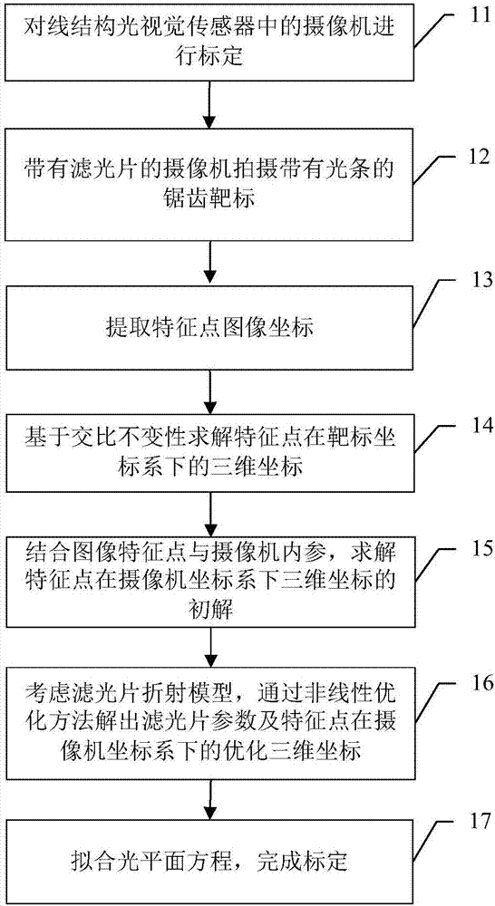
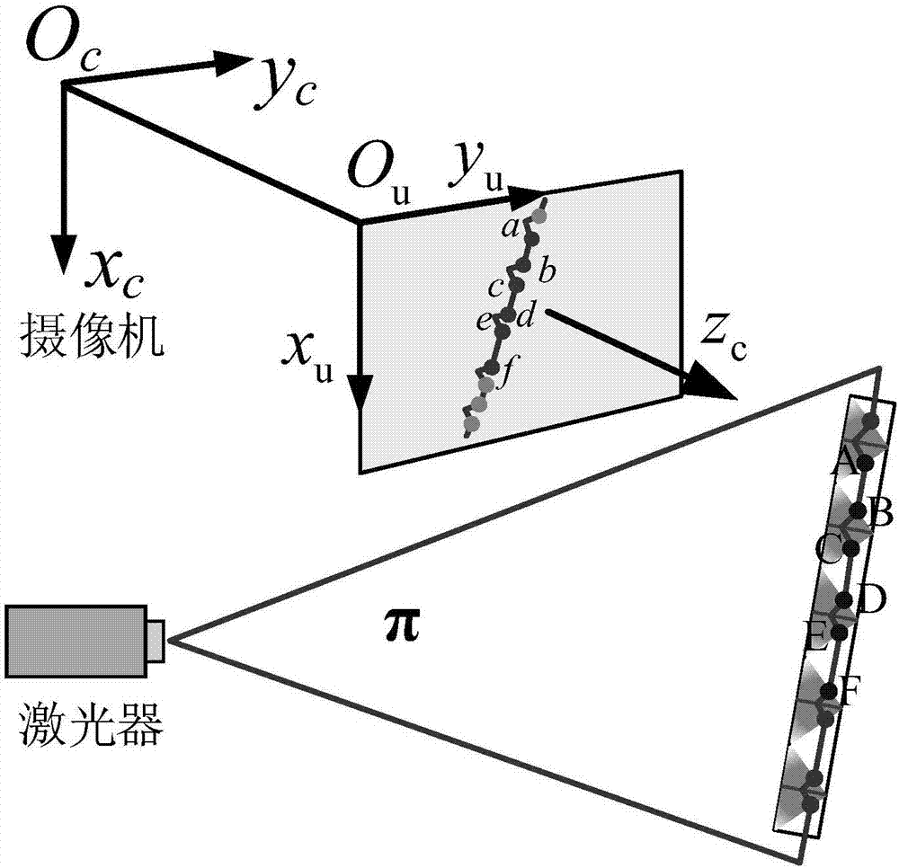
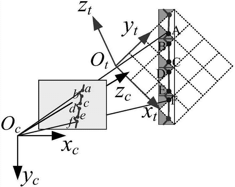
[0027] The basic idea of ​​the present invention is: based on the constant cross-ratio, solve the initial solution of the three-dimensional coordinates of the intersection point of the light strip and the jagged edge of the target, that is, the feature point in the camera coordinate system, and add the filter model, and solve the light plane equation through optimization, that is, realize Calibration of line structured light vision sensors.

[0028] Hereinafter, the present invention will be further described in detail by taking a line structured light vision sensor composed of a camera and a line laser as an example.

[0029] Such as figure 1 As shown, the calibration method of the line structured light vision sensor based on the sawtooth target of the present invention mainly includes the following steps:

[0030] Step 11: Calibrate the camera in the line structured light vision sensor without a filter.

[0031] Here, the calibration of the camera of the visual sensor is t...


PUM


Abstract

The present invention discloses a line structured light visual sensor calibration method based on a sawtooth target. The method comprises: in the condition that a camera has no an optical filter, performing calibration of the camera in a line structured light visual sensor; installing an optical filter at the front portion of the camera lens, allowing the camera to shoot a sawtooth target image with a light bar, obtaining image coordinates of the intersection point of the light bar and the target tooth-shaped edge, namely the image coordinates of feature points, and solving the three-dimensional coordinates of the feature points in the camera coordinate system based on the principle of cross-ratio invariance; considering an optical filter refraction model, and solving the parameters of the optical fiber and the three-dimensional coordinates of the feature points after optimization in the camera coordinate system through the nonlinear optimization method; and moving the target for more than two times, obtaining the three-dimensional coordinates of all the position feature points of the target in the camera coordinate system, fitting the three-dimensional coordinate points to solve a light plane equation, and completing the calibration. The line structured light visual sensor calibration method based on the sawtooth target is suitable for a field complex light environment and even can complete line structured vision sensor calibration in the condition that the camera has the optical filter.

Description

technical field [0001] The invention relates to the technical field of sensor calibration, in particular to a calibration method for line structured light vision sensors based on sawtooth targets. Background technique [0002] Structured light 3D vision measurement can achieve large-scale, non-contact, fast and high-precision measurement in industrial environments, so it is widely used. The line structured light method and the grating structured light method are visual sensors composed of lasers and cameras, which can be used to measure the three-dimensional shape of objects in complex environments. [0003] The calibration process of line structured light vision sensor includes camera internal parameter calibration and light plane parameter calibration. Among them, there are many studies on camera internal parameter calibration, so we focus on the light plane parameter calibration process. There are many methods for calibrating the light plane parameters. For example, De...

Claims


Application Information

Patent Timeline
IPC IPC(8): G01B11/24
CPCG01B11/24
Inventor 刘震武群潘晓
Owner BEIHANG UNIV
Learn More