Position sensorless control system commutation control method for brushless direct-current motor

A technology of brushless DC motor and control system, applied in control system, electronic commutation motor control, electronic commutator, etc., can solve the inaccurate measurement angle, limit the application of brushless DC motor, and control system without position sensor Inaccurate commutation, etc.

Active Publication Date: 2017-09-29
HARBIN ENG UNIV
View PDF5 Cites 16 Cited by
  • Summary
  • Abstract
  • Description
  • Claims
  • Application Information

AI Technical Summary

Problems solved by technology

However, in the process of obtaining the back electromotive force, due to the lag generated by the filter, the PWM dead time, and the quantization error of the ADC, the commutation of the sensorless control system will be inaccurate, which limits the high precision of the brushless DC motor. Occasion application
[0003] Liu Gang and others published the "Closed-loop correction strategy for positionless commutation error of high-speed magnetic levitation brushless DC motor" in the Journal of Electrotechnical Society. This document uses the curr

Method used


Image

  • Position sensorless control system commutation control method for brushless direct-current motor
  • Position sensorless control system commutation control method for brushless direct-current motor
  • Position sensorless control system commutation control method for brushless direct-current motor

Examples


Embodiment

[0073] The specifications of the brushless DC motor used in the present invention are shown in Table 1:

[0074] Table 1. Motor specifications and parameters

[0075]

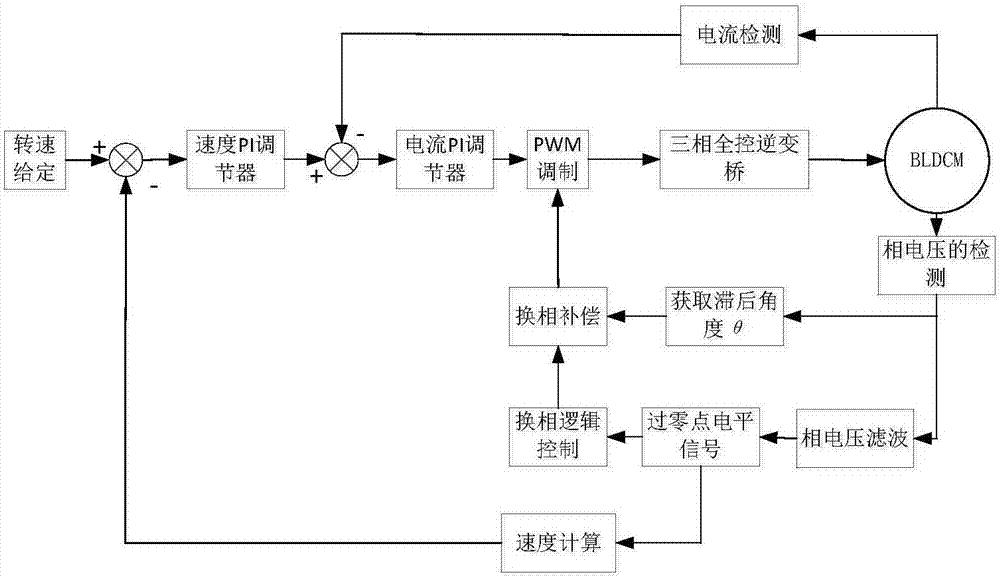
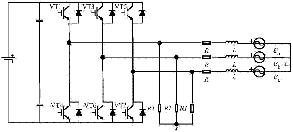
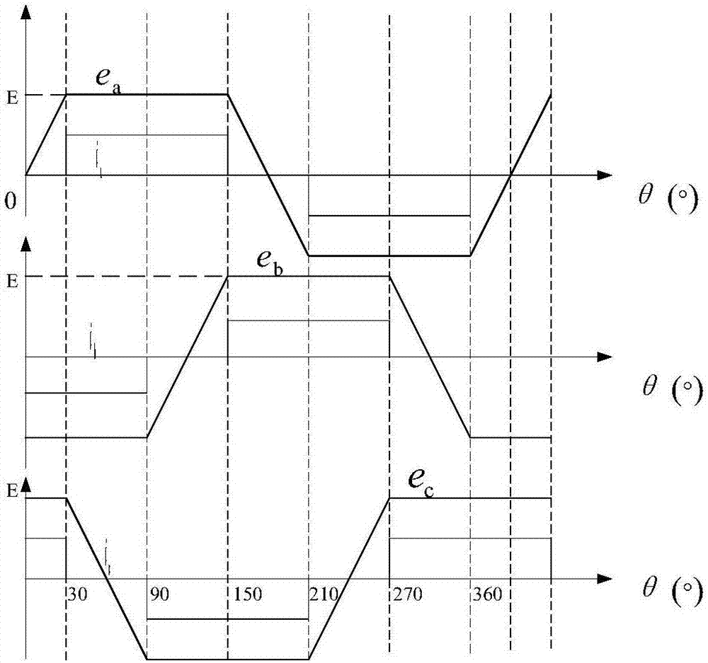
[0076] Such as figure 2 As shown, the three-phase winding of the DC brushless motor adopts a star-shaped connection structure, and the three-phase fully-controlled bridge inverter circuit adopts a two-to-two conduction mode, each power tube conducts 120°, and commutates once every 60° electrical angle . The DC brushless motor used is a trapezoidal wave with a counter electromotive force of 120° and a flat top, and the modulation method used is the Hpwm-Lon modulation method. Construct a fictitious neutral point, compare the terminal voltage with the fictitious midpoint to obtain the waveform obtained by filtering the phase voltage, take its zero-crossing time, and then delay 30° to be the commutation point of the brushless DC motor. However, due to the delay caused by the filter circuit and the system, t...


PUM


Abstract

The invention provides a position sensorless control system commutation control method for a brushless direct-current motor. The brushless direct-current motor is connected with a three-phase fully-controlled bridge inverter circuit, the three-phase fully-controlled bridge inverter circuit is used for driving the position sensorless control brushless direct-current motor to work, the phase voltage of the brushless direct-current motor is acquired by virtually constructing neutral point of the motor again, the phase voltage of the brushless direct-current motor is collected through a position detection module, the phase voltage is filtered to obtain a zero crossing point, the rotor position information of the brushless direct-current motor is acquired, the angular difference of the current rotor commutation position and the optimal commutation position is calculated by using a position compensating module, and angle compensation is carried out in the next period. According to the method, the phenomenon that upwarp does not appear on current waveform before and after each conduction period is pushed, so that minimum torque ripple is realized. According to the control system realized by using simulation means, after errors are detected by the system, corresponding compensation is carried out in subsequent commutation period, and the result indicates feasibility and effectiveness of the method.

Description

technical field [0001] The invention relates to a method for precisely commutating the phases of a position sensorless control system of a DC brushless motor. Background technique [0002] Brushless DC motor not only has the good speed regulation performance of DC motor, stable operation, and simple control method, but also has the advantages of brushless AC servo system, small size, and stable operation in harsh environments. Therefore, it has a wide range of applications in aerospace, electric vehicles, home appliances and other fields. The DC brushless motor control system must detect the position of the rotor and perform accurate commutation. In this process, the position sensor is necessary. The common DC brushless motor relies on the Hall-type position sensor to detect the rotor position, but Such magnetic sensitive components are easily disturbed by the external environment, which limits the application range of the brushless DC motor control system. In this backgro...

Claims


Application Information

Patent Timeline
IPC IPC(8): H02P6/182H02P6/14
CPCH02P6/14H02P6/182
Inventor 姚绪梁林浩江晓明鲁光旭张永奇王峰胡心达李宏运常英健张燕
Owner HARBIN ENG UNIV
Why Eureka
Try Eureka