
Oil coating equipment used for production and manufacturing of motor rotor

A motor rotor and oiling technology, which is applied in the manufacture of motor generators, stator/rotor bodies, coatings, etc., can solve the problems of low efficiency, decreased consistency of finished product quality, and labor-intensive problems

Inactive Publication Date: 2017-10-03
黄志洁
View PDF4 Cites 6 Cited by
  • Summary
  • Abstract
  • Description
  • Claims
  • Application Information

AI Technical Summary

Problems solved by technology

[0002] When the motor rotor is being processed, it is necessary to apply anti-rust oil on the shaft and iron core at both ends of the motor to prevent the iron core and shaft from rusting; usually this process is completed on a special machine, which includes the main motor, driving shaft, The tail shaft, thimble, bracket and oiling device, among which the oiling device of the machine is fixed, so when processing other processes, the motor rotor must be frequently replaced by the machine station. This mode of work is not only inefficient, but also labor-intensive. Frequent changes of workstations also lead to a decline in the consistency of finished product quality

Method used


Image

  • Oil coating equipment used for production and manufacturing of motor rotor
  • Oil coating equipment used for production and manufacturing of motor rotor
  • Oil coating equipment used for production and manufacturing of motor rotor

Examples


Embodiment Construction

[0021] The technical solution of this patent will be described in further detail below in conjunction with specific embodiments.

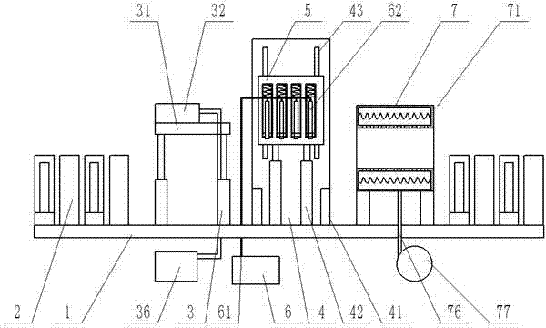
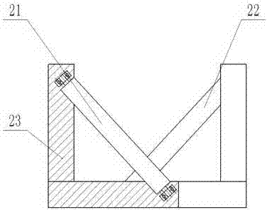
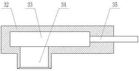
[0022] See Figure 1-5 , An oiling equipment for the production and manufacture of motor rotors, including a worktable 1, a dust removal device 3, and an oiling device and a drying device 7. The worktable 1 is symmetrically provided with two supporting roller groups 2 and supporting roller groups 2 Including a first supporting roller 21 and a second supporting roller 22 arranged relatively obliquely, each of the first supporting roller 21 and the second supporting roller 22 is provided with four; the first supporting roller 21 and the second supporting roller 22 both pass through the L-shaped The bracket 23 is installed on the table surface of the workbench 1, the L-shaped bracket 23 is fixedly connected to the workbench 1 by bolts, the first supporting roller 21 and the second supporting roller 22 are rotatably connected to the L-shaped bracket 23, a...


PUM


Abstract

The invention discloses oil coating equipment used for production and manufacturing of a motor rotor. The oil coating equipment comprises a working table, a dust removing apparatus and an oil coating apparatus drying apparatus; two supporting roller groups are symmetrically arranged on the working table; the supporting roller groups comprise four first supporting rollers and four second supporting rollers which are arranged in an inclined manner; the first supporting rollers and the second supporting rollers are all mounted on the table surface of the working table through L-shaped brackets; the L-shaped brackets are fixedly connected with the working table through bolts; and the first supporting rollers and the second supporting rollers are rotationally connected with the L-shaped brackets. Along with left and right movement and rotation of the motor rotor, it is ensured that an oil coating needle can be attached to the surface of the motor rotor through a compression spring, so that the oil coating needle can coat oil on the motor rotor in an all-around and uniform manner; and an induced draft fan works to introduce external air from a hot air inlet pipe, and then the air enters a heating cavity to take the heat in the heating cavity out of a hot air outlet, so that the drying effect can be reinforced.

Description

Technical field [0001] The invention relates to the field of electronic industrial equipment manufacturing, in particular to an oiling equipment used for the production and manufacture of motor rotors. Background technique [0002] When the motor rotor is processed, it is necessary to apply anti-rust oil on the rotating shaft and iron core at both ends of the motor to prevent the iron core and rotating shaft from rusting; usually this process is completed on a special machine, which includes the main motor, driving shaft, The tail shaft, thimble, bracket and oiling device, among which the oiling device of the machine is fixed, so when processing other processes, it is necessary to frequently replace the machine station of the motor rotor. This working mode is not only inefficient, but also labor-intensive. Frequent changes of workstations also lead to a decrease in the consistency of finished product quality. Summary of the invention [0003] The purpose of the present invention ...

Claims


Application Information

Patent Timeline
Patent Type & Authority Applications(China)
IPC IPC(8): H02K15/02H02K15/12B05C5/00B05C13/02B05C9/14B05D3/04B05D3/00
CPCH02K15/02B05C5/002B05C9/14B05C13/02B05D3/002B05D3/0413H02K15/12
Inventor 黄志洁
Owner 黄志洁
Learn More