
Substance refractive index remote measuring device and measuring method thereof

A technology for remote measurement and refractive index, applied in the field of remote measurement of material refractive index based on cross-correlation optical time-domain Fresnel reflection technology

Inactive Publication Date: 2017-10-10
TAIYUAN UNIV OF TECH
View PDF9 Cites 1 Cited by
  • Summary
  • Abstract
  • Description
  • Claims
  • Application Information

AI Technical Summary

Problems solved by technology

[0003] The technical problem to be solved by the present invention is: how to solve the problem of measuring the refractive index of materials in remote harsh environments

Method used

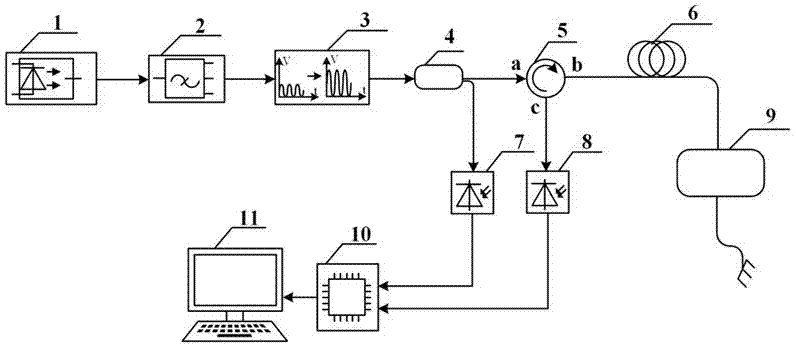

Image

  • Substance refractive index remote measuring device and measuring method thereof
  • Substance refractive index remote measuring device and measuring method thereof
  • Substance refractive index remote measuring device and measuring method thereof

Examples


Embodiment approach 1

[0018] Such as figure 1 with figure 2 As shown, a remote measurement device for the refractive index of a substance mainly includes a broadband amplified spontaneous radiation source 1, a dense wavelength division multiplexer 2, an erbium-doped fiber amplifier 3, a first fiber coupler 4, an optical circulator 5, and a transmission Sensing fiber 6, first photodetector 7, second photodetector 8, sensing unit 9, acquisition card 10 and computer 11, broadband amplified spontaneous radiation source 1 is connected to the input port of dense wavelength division multiplexer 2, To filter out the noise-like optical signal near the center wavelength, connect the optical signal to the input end of the erbium-doped fiber amplifier 3, amplify it by adjusting the pump current of the erbium-doped fiber amplifier 3, and connect it to the first fiber At the input end of the coupler 4, the first fiber coupler divides it into one with 99% optical power and one with 1% optical power according to th...

Embodiment approach 2

[0028] The difference from the first embodiment is that image 3 As shown, this embodiment is another implementation of the sensing unit 9, which includes a sensing fiber 6 and a second fiber coupler 15. The optical signal transmitted by the sensing optical fiber 6 is divided into two optical signals through the second optical fiber coupler 15 according to the optical power, and one optical signal is injected into the next section of the sensing optical fiber 6 through the first output port of the second optical fiber coupler 15. The second output port of the second optical fiber coupler 15 is connected to a section of optical fiber placed in a substance with a certain refractive index.

[0029] Fresnel reflection occurs on the interface between the fiber connector of the second fiber coupler 15 and the substance 14 of a certain refractive index, and combined with the cross-correlation technology, the position where the Fresnel reflection occurs, the refractive index of the substa...


PUM


Abstract

The invention relates to the field of substance refractive index measurement, in particular to substance refractive index remote measurement based on a cross-correlation time-domain Fresnel reflection technology. A substance refractive index remote measuring device comprises a wide-band amplified spontaneous radiation source, a dense wavelength division multiplexer, an erbium-doped optical fiber amplifier, a first optical fiber coupler, an optical circulator, a sensing optical fiber, a first photoelectric detector, a second photoelectric detector, a sensing unit, an acquisition card and a computer. The invention also relates to a method using the measuring device. According to the invention, relation between the substance refractive index and the fiber core refractive index is represented by virtue of a peak value of a cross-correlation curve, in turn the substance refractive index is obtained, multi-point substance refractive index measurement in flammable, explosive and hazardous environments such as a chemical plant can be realized, and the substance refractive index remote measuring device has the advantages of safety in nature, electromagnetic interference resistance, corrosion resistance and remote measurement.

Description

Technical field [0001] The invention relates to the field of measurement of the refractive index of a substance, in particular to the remote measurement of the refractive index of a substance based on the cross-correlation optical time-domain Fresnel reflection technology. Background technique [0002] As the intrinsic properties of substances, refractive index parameters are closely related to the chemical and physical properties of substances. Therefore, in some fields, the measurement of refractive index of substances has very important research significance. However, most of the existing technologies are electronic sensors for short-range measurement, which cannot well meet the requirements for measuring the refractive index of substances in harsh environments such as electromagnetic interference, corrosion, flammability and explosion. Summary of the invention [0003] The technical problem to be solved by the present invention is: how to solve the problem of measuring the ref...

Claims


Application Information

Patent Timeline
Patent Type & Authority Applications(China)
IPC IPC(8): G01N21/41
CPCG01N21/41G01N2201/088
Inventor 王东张瑜靳宝全王云才王宇张明江张红娟
Owner TAIYUAN UNIV OF TECH
Learn More