Low-profile double-frequency ultra-wideband antenna

An ultra-wideband antenna and low-profile technology, applied in the field of low-profile dual-band ultra-wideband antennas, can solve the problems of inability to meet the design requirements of micro-base station antennas, difficulties in full-band ultra-wideband, and high vertical height of antennas, achieving clear principles and low cost , to achieve a simple effect

Active Publication Date: 2017-10-10
TONGYU COMM INC
View PDF8 Cites 5 Cited by
  • Summary
  • Abstract
  • Description
  • Claims
  • Application Information

AI Technical Summary

Problems solved by technology

However, for micro base station antennas whose size, especially the vertical height, is strictly limited, it will be extremely difficult to achieve full-band ultra-wideband (698-960MHz / 1710-2700MHz)
Conventional oscillators only cover high-frequency or low-frequency bands, and are about a quarter of a wavelength away from the floor, which makes the vertical height of the antenna very high (about 0.25·λL), which cannot meet the design requirements of the low profile of the micro base station antenna
[0003] Nevertheless, the outstanding advantages of crossed oscillator ultra-wideband and ±45° dual polarization make it one of the preferred solutions suitable for micro base station antennas, but it is necessary to break through the technical bottleneck of too high profile

Method used


Image

  • Low-profile double-frequency ultra-wideband antenna
  • Low-profile double-frequency ultra-wideband antenna
  • Low-profile double-frequency ultra-wideband antenna

Examples


Embodiment Construction

[0046] The preferred embodiments of the invention patent are given below in conjunction with the accompanying drawings to describe the technical solution of the present invention in detail. Here, the present invention will be described in detail with reference to the accompanying drawings. It should be noted that the preferred implementation examples described here are only used to illustrate and explain the present invention, and are not used to limit or limit the present invention.

[0047] see Figure 1-11 , the design method of described low-profile dual-frequency ultra-wideband antenna comprises the steps:

[0048] The low-profile dual-frequency ultra-wideband antenna of the present invention, the design method of the low-profile dual-frequency ultra-wideband antenna includes the following steps:

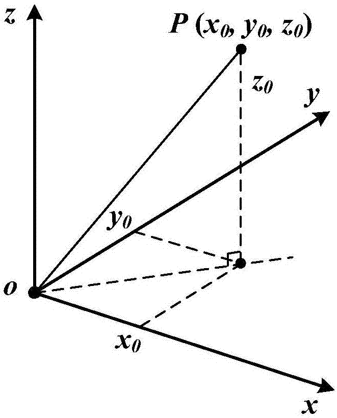
[0049] Step 1, establish a space Cartesian coordinate system, see figure 1 ;

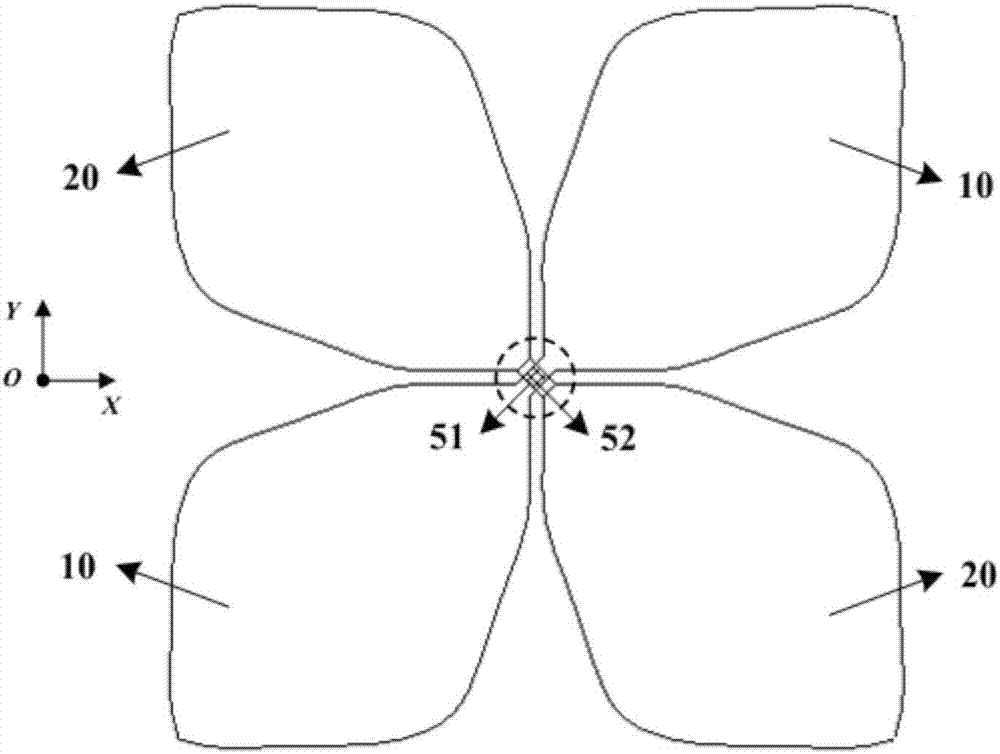
[0050] Step 2, constructing a dual-frequency ultra-broadband oscillator unit: First, on the X...


PUM


Abstract

The present invention provides a low-profile double-frequency ultra-wideband antenna, which comprises at least one double-frequency ultra-wideband vibrator unit. The double-frequency ultra-wideband vibrator unit comprises a pair of ultra-wideband vibrators printed on a dielectric substrate and arranged in an orthogonal manner. The two arms of each ultra-wideband vibrator are of a fat-block shape, and the two arms of each ultra-wideband vibrator are provided with arc grooves at the ends along the edges at two sides. The end of each ultra-wideband vibrator is loaded with a section of arc branch knot along the outer edges of the vibrator arms. The centrally intersecting part is provided with a feeding point connected coaxial cable or a balancing device. According to the invention, through the adoption of a thick highly-dielectric-constant dielectric substrate and the use of the manner of opening grooves on the vibrator surface and the loading of open circuit branch knot at the end, it is possible to provide for a micro base station of mobile communications a low-profile double-frequency ultra-wideband antenna featuring a low profile, a small size, the realization of MIMO, high separation and a high gain. The method is also innovative in idea, clear in principle, suitable for use and easy for implementation. With a low cost, the antenna can be produced in batches, and it can best replace a traditional Small Cell antenna. In addition, for the design and improvement in a traditional wideband intersecting vibrator antenna, the invention can also apply effectively.

Description

【Technical field】 [0001] The invention relates to a mobile communication antenna device and technology, in particular to a low-profile dual-band ultra-wideband antenna and its technology. 【Background technique】 [0002] At present, mobile communication is in the era of large-scale commercial use of 4G, and is gradually evolving towards 5G. Through the construction of a large number of macro base stations, mobile communications have basically achieved continuous coverage of wide-area signals. The macro base station has high gain, large capacity, large coverage area, and large number of users, but it is difficult to select a site, high cost, low data rate, and it is difficult to cover local hot spots such as indoors and underground. Cellular networks rely on cell division to achieve frequency reuse. Naturally, in order to further improve the degree of frequency reuse, people divide the cell into microcells, nanocells, picocells, etc. with smaller coverage, thereby significan...

Claims


Application Information

Patent Timeline
Patent Type & Authority Applications(China)
IPC IPC(8): H01Q1/38H01Q1/36H01Q1/50H01Q5/20
CPCH01Q1/36H01Q1/38H01Q1/50H01Q5/20
Inventor 李道铁吴中林刘木林
Owner TONGYU COMM INC
Why Eureka
Try Eureka