
Corrosion resisting insulation medium voltage switch cabinet

A corrosion-resistant, switchgear technology, applied in anti-corrosion coatings, coatings, substation/distribution device casings, etc., can solve the problem that medium-voltage switchgear does not have intelligent management, cannot meet the intelligent management of power grid, and the service life of switchgear Short and other problems, to achieve the effect of compact structure, convenient wiring, protection and safety

Pending Publication Date: 2017-10-10
JIANGSU SHENFEI ELECTRICAL TECH CO LTD
View PDF4 Cites 1 Cited by
  • Summary
  • Abstract
  • Description
  • Claims
  • Application Information

AI Technical Summary

Problems solved by technology

[0002] Due to the rapid development of my country's economy, my country's power supply grid has achieved unprecedented improvement in terms of hardware facilities and software management of the grid. Smart grids have gradually entered my country's power system. A large number of medium-voltage switchgears are important power supplies for the grid. Basic equipment, the traditional medium-voltage switchgear generally does not have intelligent management functions, and the structure is complex, there are certain hidden dangers in operation safety, which cannot meet the intelligent management of my country's modern power grid, and the existing switchgear has a short service life and is durable. less corrosive

Method used


Image

  • Corrosion resisting insulation medium voltage switch cabinet

Examples


Embodiment 1

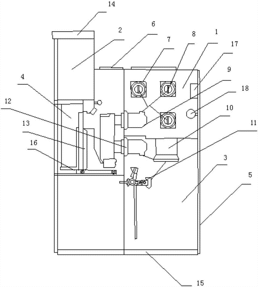
[0033] This embodiment provides a medium voltage switchgear with a structure such as figure 1 As shown, including cabinet 5, busbar room 1, circuit breaker room 4, cable room 3, relay instrument room 2 and base 15, bus bar room 1, circuit breaker room 4, cable room 3 and relay instrument room 2 are all set in the cabinet In the body 5, each chamber is separated by a detachable partition. The busbar room 1 is set above the cabinet body, and the cable room 3 is set on the lower side of it. The circuit breaker room 4 is set on the side of the busbar room. A relay instrument room 2 is set on the side, and a small busbar room 14 is arranged on the top of the relay instrument room 2. Both the relay instrument room and the cable room are equipped with doors, and the door of the instrument room is equipped with secondary components for control and display. The top of the busbar chamber 1 and the circuit breaker chamber 4 is provided with a pressure relief device 6, and both the circui...

Embodiment 2

[0045] This embodiment provides a medium voltage switchgear with a structure such as figure 1 As shown, including cabinet 5, busbar room 1, circuit breaker room 4, cable room 3, relay instrument room 2 and base 15, bus bar room 1, circuit breaker room 4, cable room 3 and relay instrument room 2 are all set in the cabinet In the body 5, each chamber is separated by a detachable partition. The busbar room 1 is set above the cabinet body, and the cable room 3 is set on the lower side of it. The circuit breaker room 4 is set on the side of the busbar room. A relay instrument room 2 is set on the side, and a small busbar room 14 is arranged on the top of the relay instrument room 2. Both the relay instrument room and the cable room are equipped with doors, and the door of the instrument room is equipped with secondary components for control and display. The top of the busbar chamber 1 and the circuit breaker chamber 4 is provided with a pressure relief device 6, and both the circui...


PUM


Abstract

The invention discloses a corrosion resisting insulation medium voltage switch cabinet comprising a cabinet body, a bus room, a breaker room, a cable room, a relay meter room and a pedestal; the pedestal is arranged on the cabinet body bottom; the bus room, the breaker room, the cable room and the relay meter room are arranged in the cabinet body; the bus room is arranged on the upper portion in the cabinet body; the cable room is arranged below the bus room; the breaker room is arranged on one side of the bus room; the relay meter room is arranged above the breaker room; the corrosion resisting insulation medium voltage switch cabinet is simple in structure, reasonable in distribution, safe in operations, corrosion resisting, and long in life.

Description

technical field [0001] The invention relates to electric power supply equipment, in particular to a corrosion-resistant and insulated medium-voltage switchgear. Background technique [0002] Due to the rapid development of my country's economy, my country's power supply grid has achieved unprecedented improvement in terms of hardware facilities and software management of the grid. Smart grids have gradually entered my country's power system. A large number of medium-voltage switchgears are important power supplies for the grid. Basic equipment, the traditional medium-voltage switchgear generally does not have intelligent management functions, and the structure is complex, there are certain hidden dangers in operation safety, which cannot meet the intelligent management of my country's modern power grid, and the existing switchgear has a short service life and is durable. Less corrosive. Contents of the invention [0003] The technical problem to be solved by the present inv...

Claims


Application Information

Patent Timeline
IPC IPC(8): H02B1/30C09D163/00C09D109/02C09D123/06C09D127/06C09D161/14C09D5/08C09D5/25C09D7/12
CPCH02B1/30C09D163/00C09D5/08C08K2201/011C08K2201/014C08K2003/2244C08K2003/2227C08K2003/2206C08K2003/2296C08L2203/20C08L2201/02C08L2205/035C08L9/02C08L23/06C08L27/06C08L61/14C08K13/02C08K3/2279C08K3/08C08K3/22C08K3/36C08K3/34
Inventor 韦艳张克俊赵梅
Owner JIANGSU SHENFEI ELECTRICAL TECH CO LTD
Learn More