
Micro lens and sample table locking system based on atomic force probe

A technology of locking system and sample stage, which is applied in the field of microscope lens and sample stage locking system, can solve the problems of low precision, high cost, complex hardware, etc., and achieve the effect of high working precision, easy construction and simple system

Pending Publication Date: 2017-10-13
CHINA JILIANG UNIV
View PDF0 Cites 0 Cited by
  • Summary
  • Abstract
  • Description
  • Claims
  • Application Information

AI Technical Summary

Problems solved by technology

[0003] The present invention proposes a novel sample locking system based on an atomic force probe, aiming at the problems of complex hardware, low precision and high cost existing in the existing focus locking device

Method used


Image

  • Micro lens and sample table locking system based on atomic force probe
  • Micro lens and sample table locking system based on atomic force probe
  • Micro lens and sample table locking system based on atomic force probe

Examples


Embodiment Construction

[0031] The present invention will be described below in conjunction with the accompanying drawings, but the present invention is not limited thereto.

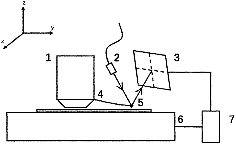
[0032] Such as figure 1 Shown is a schematic diagram of the atomic force probe-based microscope lens and sample stage locking system, including microscope lens 1, laser 2, four-quadrant detector 3, probe cantilever 4, atomic force probe 5, sample stage 6, and control unit 7 ;

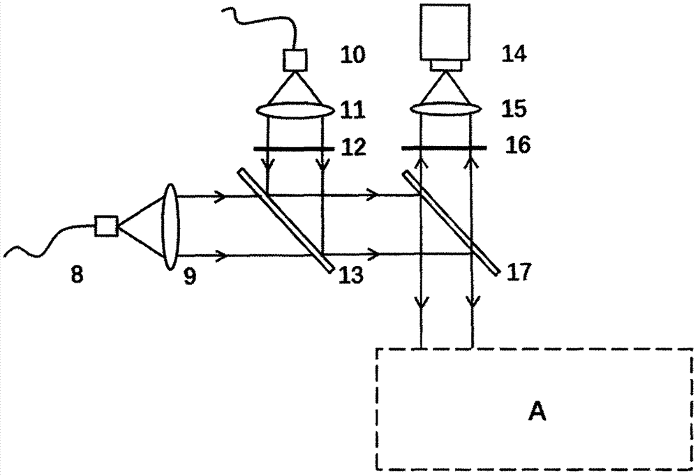
[0033] Such as figure 2 Shown is an optical path diagram of an embodiment of the device of the atomic force probe-based microscope lens and sample stage locking system of the present invention, which embodiment includes:

[0034] The device A of the microscope lens and sample stage locking system based on the atomic force probe, the excitation light source 8, the first lens 9, the loss light source 10, the second lens 11, the phase plate 12, the first dichromatic mirror 13, the detector 14, the second Three lens 15, optical filter 16, the second dich...


PUM


Abstract

The invention discloses a sample locking system based on an atomic force probe. The system comprises a micro lens, a laser, a four-quadrant detector, a probe cantilever, the atomic force probe, a sample table and a control unit. According to the system, the atomic force probe is used, the mutual action force between atoms is used to lock the relative position of the micro lens to the sample table, the system is simple, the cost is low, and the system is easy to build. According to the system, image distortion caused by the relative position change between the lens and the sample table can be overcome, and the working precision of a super-resolution microscope system is improved.

Description

technical field [0001] The invention relates to the fields of optical instruments and biomedical microscopic imaging, in particular to an atomic force probe-based microscopic lens and sample stage locking system. Background technique [0002] At present, research in the field of biomedicine requires higher and higher resolution of the microscope. Researchers need to understand the three-dimensional structure of various microscopic substances. The spot size of traditional white-light wide-field microscopes and laser confocal microscopes cannot achieve such resolution. , and the emergence of super-resolution microscopy system perfectly solves this problem. Nowadays, the mainstream super-resolution microscopy methods at home and abroad mainly focus on various fluorescence microscopy techniques, such as structured light illumination (SIM), stimulated depletion microscopy (STED), ground state depletion microscopy (GSD), etc. . Compared with ordinary microscopes, super-resolutio...

Claims


Application Information

Patent Timeline
Patent Type & Authority Applications(China)
IPC IPC(8): G01Q60/38
CPCG01Q60/38
Inventor 李旸晖刘小煜来邻
Owner CHINA JILIANG UNIV
Learn More