Nanometer iron powder light igniting device

A technology of nano-iron powder and ignition device, which is applied in the field of optical ignition, can solve the problems of bulky ignition device and difficult ignition, and achieve the effect of simple structure, easy recovery and large heat release

Pending Publication Date: 2017-10-17
NANJING UNIV OF SCI & TECH
View PDF4 Cites 2 Cited by
  • Summary
  • Abstract
  • Description
  • Claims
  • Application Information

AI Technical Summary

Problems solved by technology

Moreover, most of the ignition devices are heavy and expensive,

Method used


Image

  • Nanometer iron powder light igniting device
  • Nanometer iron powder light igniting device
  • Nanometer iron powder light igniting device

Examples


Embodiment Construction

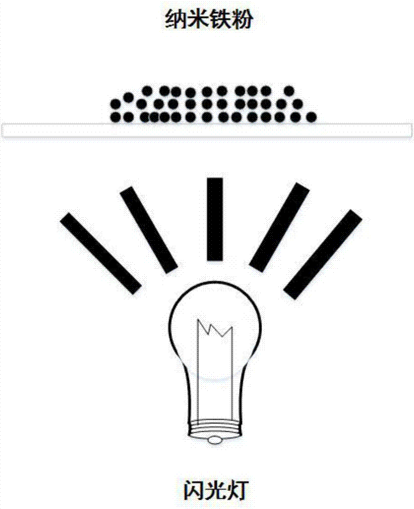
[0011] combine figure 1 , a nano-iron powder optical ignition device, which uses a flash lamp 1 to release light pulse energy in a very short time, and the nano-iron powder 3 absorbs the light energy. At this time, the oxide layer on the surface of the nano-iron powder 3 is destroyed, so that the inner nano-iron particles It reacts with the surrounding air and releases heat to achieve the purpose of ignition.

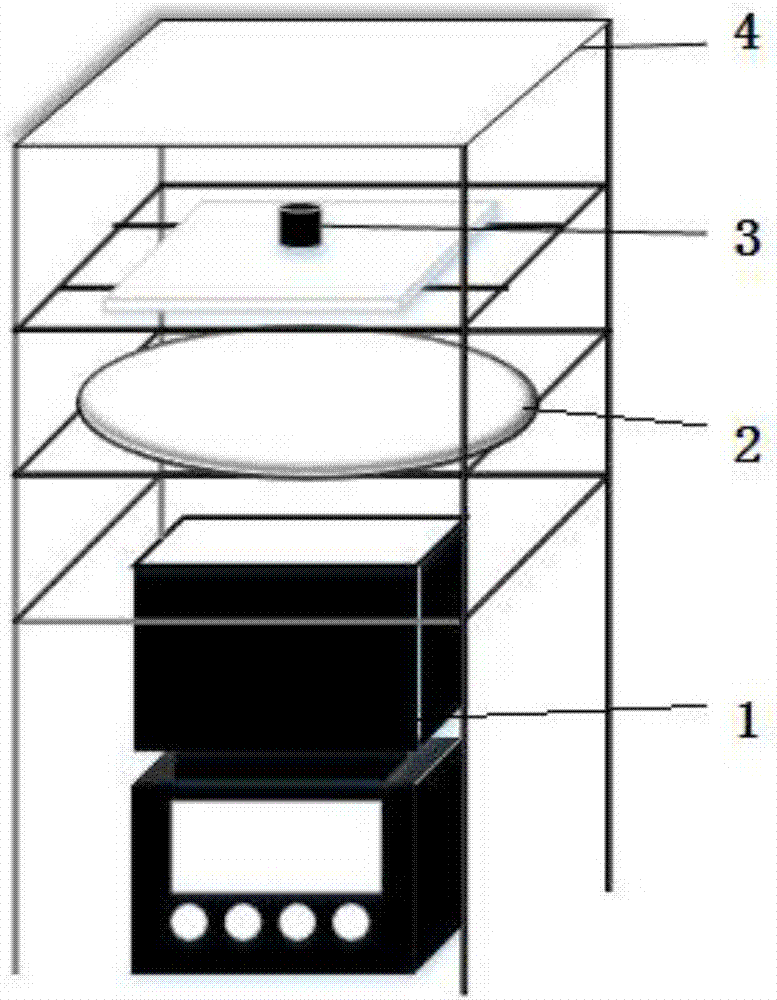
[0012] combine figure 2 , a nano-iron powder light ignition device is divided into two parts: a light source and a light intensifier. The hardware of the system mainly includes two parts: a flashlight 1 located under the material, a reflector 4 and a condenser 2 for light intensification. The nanostructure material is exposed to the light source of ordinary flashlight, and the divergent natural light gathers energy through the condenser 2, and at the same time, part of the light scattered to the surrounding is absorbed by the nanomaterial through the reflection of the...


PUM


Abstract

The invention provides a nanometer iron powder light igniting device which comprises a flashlight and nanometer iron powder. The flashlight releases light pulse energy in an ultra-short time, the nanometer iron powder absorbs the light energy, oxide layer on the surface of the nanometer iron powder is destroyed, and so that nanometer iron particles in the nanometer iron powder reacts with surrounding air.

Description

technical field [0001] The invention relates to an optical ignition technology, in particular to a nanometer iron powder optical ignition device. Background technique [0002] The non-contact ignition and optimal control of nano-solid materials is the most complicated part. At present, most of the fuels commonly used are liquid fuels such as gasoline and diesel. As a new type of fuel, nanomaterials can quickly undergo a strong oxidation reaction to release a large amount of heat after being ignited, and can reach extremely high temperatures in an instant. [0003] The commonly used ignition technology is mainly divided into direct ignition and indirect ignition. Direct ignition such as electric spark ignition relies on equipment to generate extremely high temperature to ignite fuel, while indirect ignition such as plasma ignition relies on fuel absorbing energy to reach the ignition point for combustion. Light ignition is also a kind of indirect ignition method. The main d...

Claims


Application Information

Patent Timeline
IPC IPC(8): F23Q13/00
CPCF23Q13/005
Inventor 刘冬刘彦雄刘冠楠
Owner NANJING UNIV OF SCI & TECH
Why Eureka
Try Eureka