Multifunctional following optical cable welding workbench

A multi-functional, workbench technology, applied in the direction of light guide, optics, optical components, etc., can solve the problems of increasing the labor burden of operators, reducing work efficiency, and inconvenient portability, so as to facilitate fault analysis and file establishment, and improve work efficiency , the effect of saving energy

Pending Publication Date: 2017-10-17
RES INST OF ECONOMICS & TECH STATE GRID SHANDONG ELECTRIC POWER +1
View PDF2 Cites 1 Cited by
  • Summary
  • Abstract
  • Description
  • Claims
  • Application Information

AI Technical Summary

Problems solved by technology

[0002] In recent years, the field of telecommunications has developed rapidly, and the amount of optical fiber connections has increased sharply. At present, when performing optical cable fusion construction operations, operators often need to manually carry optical cable fusion splicers, wire strippers, optical time domain reflectometers, multimeters and other equipment to the work site. There are many types and inconvenient to carry, which greatly increases the labor burden of the operators, especially in the field repair work. At the same time, because there is no special workbench for optical cable fusion, when performing fiber core splicing, the fusion splicer and the optical cable splicing box are often placed On the ground, it is easy to cause core breakage and large loss when the optical cable is welded; when the welding operation is carried out for a long time, it is easy to cause the machine to crash due to the high working temperature of the welding machine, which reduces the work efficiency

Method used


Image

  • Multifunctional following optical cable welding workbench
  • Multifunctional following optical cable welding workbench
  • Multifunctional following optical cable welding workbench

Examples


Embodiment approach

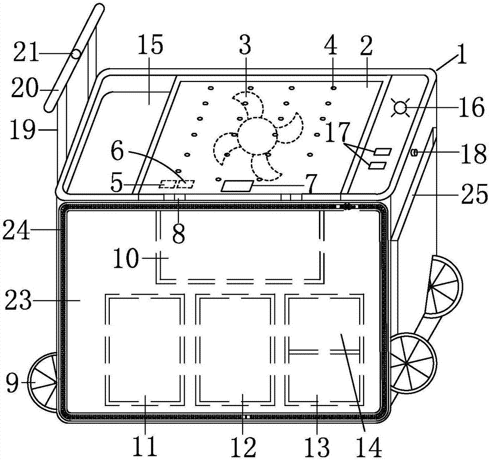
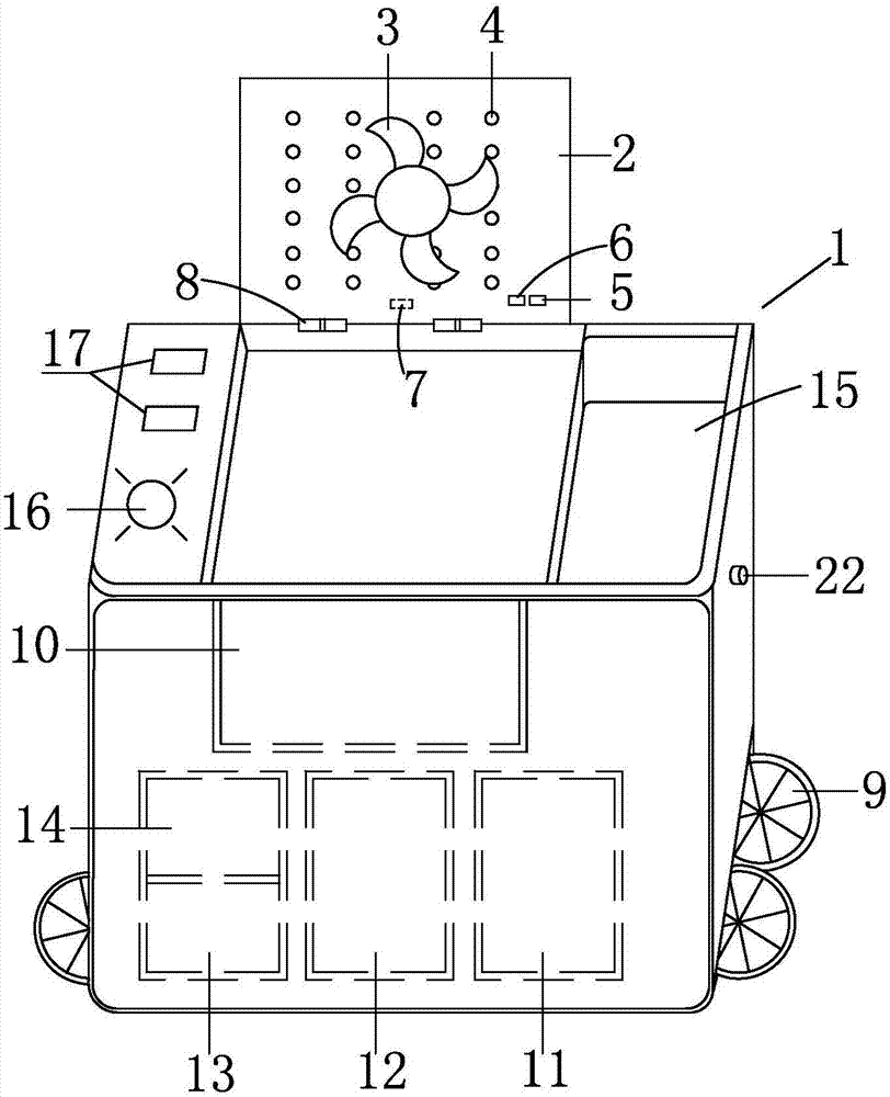
[0025] Such as Figure 1 to Figure 3 Shown: a multi-functional follow-up optical cable welding workbench, including a box body 1, the upper top surface of the box body 1 is provided with a work surface 2, and the work surface 2 is connected to the upper surface of the box body 1 through a damping hinge structure 8 The front and side edges of the top are connected, and the side of the worktable 2 facing the inside of the box body 1 is provided with a fan 3. The fan 3 is arranged in parallel with the worktop 2, and the side of the worktable 2 facing the inside of the box 1 is close to the fan. 3. A temperature sensor 5 and a temperature sensing controller 6 are also provided at the left front side. The temperature sensor 5 and the temperature sensing controller 6 are arranged horizontally. Connect with the temperature sensor 5, the temperature sensor 5 is connected with the temperature sensing controller 6 through the wire, the temperature sensing controller 6 is connected with ...


PUM


Abstract

A multifunctional following optical cable welding workbench disclosed by the present invention comprises a box body, a workbench surface is arranged at the middle position of the upper top surface of the box body and is connected with an edge at the front side of the upper top surface of the box body via a damping hinge structure, and a fan is arranged on one surface of the workbench surface facing the inner side of the box body. The fan and the workbench surface are arranged parallelly, a temperature sensor and a temperature induction controller are also arranged at the positions close to the left front side of the fan of one surface of the workbench surface facing the inner side of the box body, and a temperature display is arranged on the workbench surface and is connected with the temperature sensor via a conducting wire. The temperature sensor is connected with the temperature induction controller via a conducting wire, the temperature induction controller is connected with a speed regulation joint of a fan motor via a conducting wire and is connected with a storage battery via a conducting wire, and a plurality of radiating holes are also arranged on the workbench surface. The multifunctional following optical cable welding workbench of the present invention enables the temperature of an optical fiber welding machine to be reduced, and the working efficiency of the optical cable welding to be improved.

Description

technical field [0001] The invention relates to the technical field of optical cable welding, in particular to a multifunctional follow-up optical cable welding workbench. Background technique [0002] In recent years, the field of telecommunications has developed rapidly, and the amount of optical fiber connections has increased sharply. At present, when performing optical cable fusion construction operations, operators often need to manually carry optical cable fusion splicers, wire strippers, optical time domain reflectometers, multimeters and other equipment to the work site. Equipment There are many types and inconvenient to carry, which greatly increases the labor burden of the operators, especially in the field emergency repair work. At the same time, because there is no special workbench for optical cable fusion, when performing fiber core splicing, the fusion splicer and optical cable splicing box are often placed On the ground, it is easy to cause core breakage and...

Claims


Application Information

Patent Timeline
Patent Type & Authority Applications(China)
IPC IPC(8): G02B6/255
CPCG02B6/2553G02B6/2555G02B6/2557
Inventor 毕晓伟毕晓涛张勇刘晗张浩李菁竹孔德秋张鵾王鹏王振坤付振霄夏立磊苏乃斌刘婷田鑫刘晓明牛新生贾善杰苏静华王轶群范春磊金志强崔荣喜李彦张丞刘小伟李兴昊张丽娜
Owner RES INST OF ECONOMICS & TECH STATE GRID SHANDONG ELECTRIC POWER
Why Eureka
Try Eureka