Tandem vector thrust full-drive aircraft and its design method

An all-drive, aircraft technology, applied in the aerospace field, can solve problems such as large disturbance torque on the wing surface, uncontrollable attitude deflection of the aircraft, and uncontrollable attitude

Active Publication Date: 2019-06-28
何漠
View PDF5 Cites 0 Cited by
  • Summary
  • Abstract
  • Description
  • Claims
  • Application Information

AI Technical Summary

Problems solved by technology

[0011] Different from the tilting rotor, the tail seat UAV system has a simple structure, can meet the minimum requirements for the landing area, and can take off and land vertically and hover in the air. controlled situation
Because it has a large airfoil, most of the reasons for its instability are the interference of external airflow, especially in the hovering state, the airfoil in the wind area can easily cause a large disturbance moment, which will cause the aircraft to Uncontrollable attitude deflection

Method used


Image

  • Tandem vector thrust full-drive aircraft and its design method
  • Tandem vector thrust full-drive aircraft and its design method
  • Tandem vector thrust full-drive aircraft and its design method

Examples


specific Embodiment approach 1

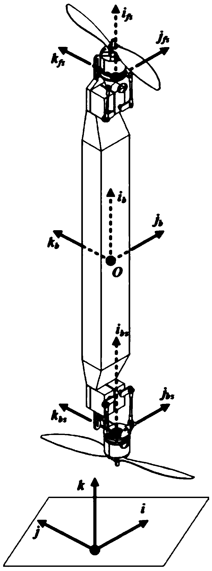
[0092] Specific implementation mode one: as Figure 1-Figure 9 As shown, this embodiment describes a tandem vector thrust full-drive aircraft, which is characterized in that: its composition includes a body 1, two electric thrust systems 3, two vector actuators 2, four steering gears 4 and two a connecting mechanism 5; the two electric thrust systems 3 are respectively a front electric thrust system and a rear electric thrust system, and the two vector actuators 2 are respectively a front vector actuator and a rear vector actuator, The four steering gears 4 are respectively two front steering gears and two rear steering gears, and the two connecting mechanisms 5 are respectively a front connecting mechanism and a rear connecting mechanism;

[0093] The front vector actuating mechanism is respectively connected with the front connecting mechanism and the front electric thrust system to form a front thrust vector actuating mechanism, and the front thrust vector actuating mechani...

specific Embodiment approach 2

[0096] Specific implementation mode two: as Figure 1-Figure 9 As shown, this embodiment is a further description of Embodiment 1. Each of the vector actuators 2 includes a phase limiter 6, a motor mounting base 7 and two connecting rods 8; the phase limiter 6 is connected with the corresponding connecting mechanism 5, the bottom of the motor of each electric thrust system 3 is fixed on the motor mount 7, one end of the two connecting rods 8 is connected with the motor mount 7, and the two connecting rods 8 and the other end is connected with the corresponding connecting mechanism 5.

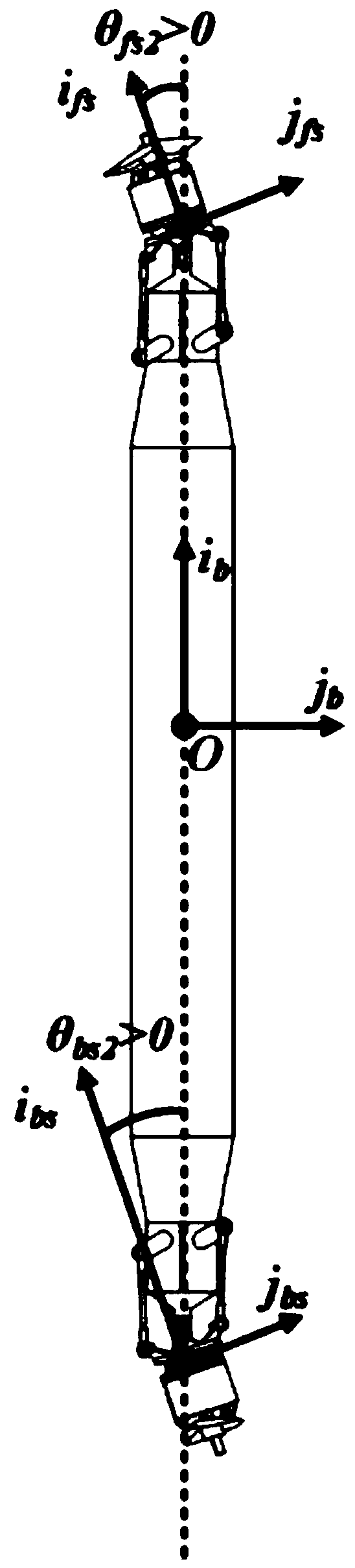
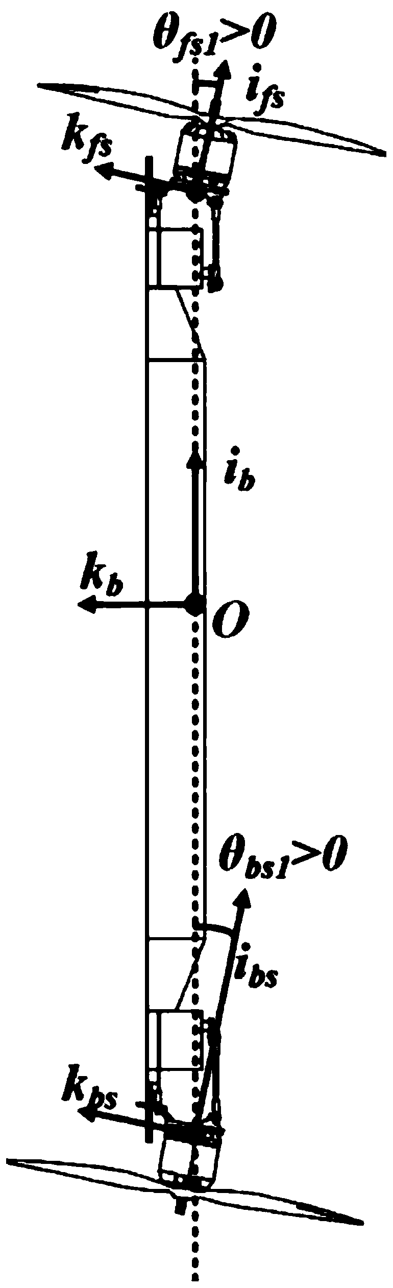
[0097] The connecting rod 8 is used to control the direction of the electric thrust vector, the phase limiter 6 is used to ensure that the motor mount 7 does not rotate; the motor mount 7 is used to connect with the electric thrust system 3 . The motor mount 7 of the vector actuator 2 is controlled by the connecting rod 8, and can form an angle with the body 1: θ 1 with theta 2 , θ 1 is the ...

specific Embodiment approach 3

[0098] Specific implementation mode three: as Figure 9 As shown, this embodiment is a further description of the second specific embodiment. The two front steering gears are connected to the two connecting rods 8 of the front vector actuator, and the two rear steering gears are connected to the rear vector The two connecting rods 8 of the actuating mechanism are connected.

[0099] The steering gear 4 is the executive mechanism that controls the vector actuator 2, and the control of the thrust vector can be realized by connecting the connecting rod 8 of the vector actuator 2, such as Figure 8 with Figure 9 shown.


PUM


Abstract

The tandem vector thrust full-drive aircraft and its design method relate to the technical field of aerospace. The front vector actuating mechanism is respectively connected with the front connecting mechanism and the front electric thrust system to form a front thrust vector actuating mechanism. The moving mechanism is respectively connected with the rear connecting mechanism and the rear electric thrust system to form a rear thrust vector actuating mechanism. The rear connecting mechanism is connected with the rear end of the body. The invention can realize the vertical take-off, landing and hovering of the aircraft, and has strong application flexibility. In addition to the vertical flight mode, it can be mounted on a fixed wing for horizontal flight, taking into account the requirements of speed and efficiency for long-distance flight. Near the working point is a full-drive system, which can directly generate lateral control force without attitude deflection, and directly perform position translation, with strong anti-interference ability and high maneuverability.

Description

technical field [0001] The invention relates to the field of aerospace technology, in particular to a tandem vector all-drive aircraft and a design method thereof. Background technique [0002] At present, for the structure of special-shaped aircraft, it mainly includes tailstock type, tilting fuselage type, tilting rotor type, etc. Among them, the tilting rotor and tilting fuselage type are relatively difficult to realize due to the need for complex rotating mechanisms. The existence of the structure leads to the limitation of its speed during level flight, making it impossible to achieve high-speed flight. For the tail seat aircraft, due to its large wing surface, the environmental factors, especially the wind factors, are relatively high during take-off and landing. Once the wind speed is high, the aircraft will not be able to take off and land smoothly. landing. [0003] In addition, currently small UAVs use an underactuated structure to control the UAV. If it is neces...

Claims


Application Information

Patent Timeline
Patent Type & Authority Patents(China)
IPC IPC(8): B64C13/50B64D27/24G06F17/50
CPCB64C13/50B64D27/24G06F30/00Y02T50/60
Inventor 何漠
Owner 何漠
Why Eureka
Try Eureka