Cover feeding mechanism

A technology of capping wheel and fixing bracket, which is applied to flange-type caps, conveyor objects, bottle/container caps, etc., can solve the problems of leaking can caps, metal cans that cannot be capped normally, and difficult to apply. , to achieve a reasonable effect of structural design

Active Publication Date: 2017-10-20
安徽金龙山葛业有限公司
View PDF7 Cites 2 Cited by
  • Summary
  • Abstract
  • Description
  • Claims
  • Application Information

AI Technical Summary

Problems solved by technology

[0002] Metal cans are widely used in our production and life. The advantages of metal cans are very obvious. Its airtight performance is very good and it can resist high internal pressure. It can ensure that the products in the metal cans are not easy to expire, and can ensure that the metal cans There is no deformation during use. During the filling and sealing process of metal cans, metal can lids are generally used to seal tightly. The existing automatic lid loading mechanism is generally only suitable for smaller can lids. Therefore, for metal cans When the bottle mouth is large and needs to be sealed with a large-sized can lid, the existing automatic capping mechanism is difficult to apply to large-sized can lids due to structural limitations. The filling of the existing wide-mouth metal cans The process generally uses an assembly line for filling. When the metal cans are filled and conveyed along the assembly line, the existing capping method is generally to manually place the can lids on the metal cans horizontally. The workers' work intensity is relatively high and often During the process of placing the metal cap, the metal cap will fall off and the metal can will be knocked over, which will affect the normal operation of the assembly line. The existing manipulator is also used to cover the can lid. The manipulator often grabs the can during the capping process. In the process of capping, the can lid is caught more or less, which leads to the failure of the metal can to be covered normally, so that the efficiency and quality of the metal can can not be guaranteed, and it cannot meet the needs of production and use.

Method used


Image

  • Cover feeding mechanism
  • Cover feeding mechanism
  • Cover feeding mechanism

Examples


Embodiment Construction

[0013] In order to further describe the present invention, a specific implementation of the upper cover mechanism will be further described below in conjunction with the accompanying drawings. The following examples are explanations of the present invention and the present invention is not limited to the following examples.

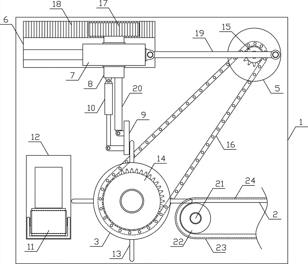
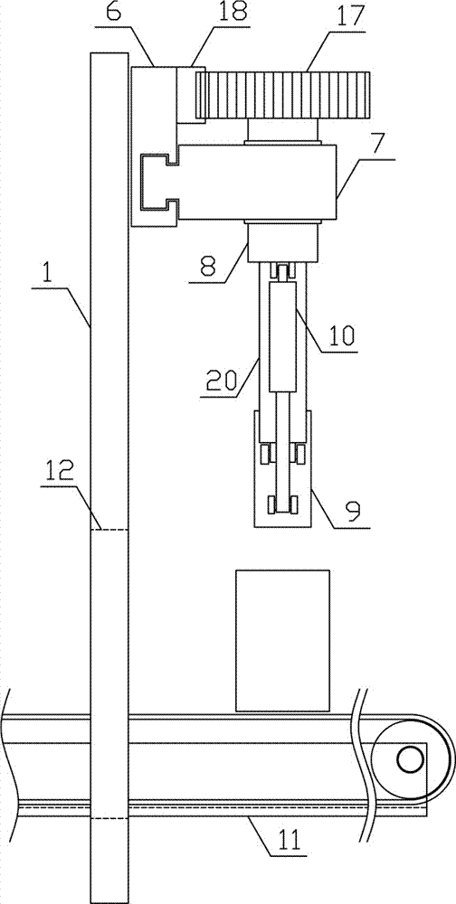
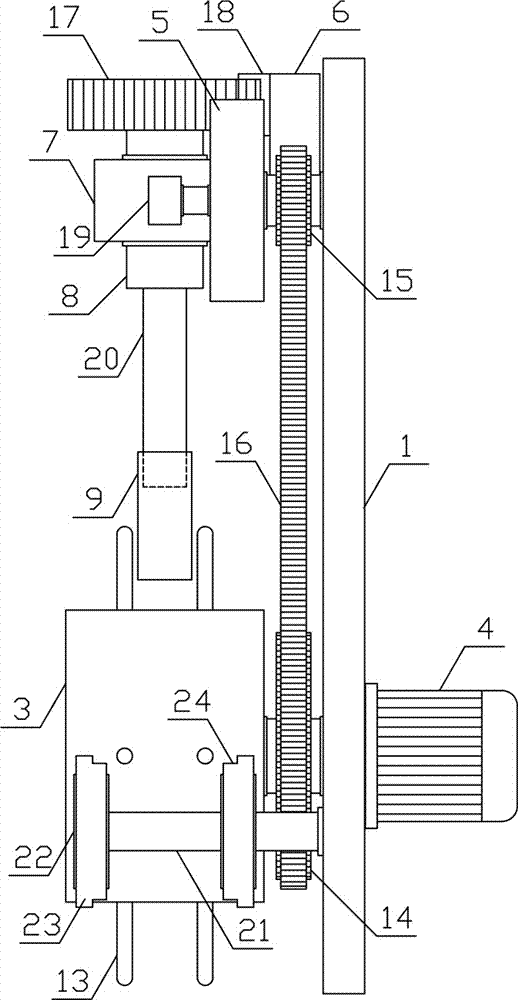
[0014] Such as figure 1 , figure 2 As shown, an upper cover mechanism of the present invention includes a fixed bracket 1, a cover transfer mechanism 2, an upper cover wheel 3, an upper cover motor 4, a rotating disc 5, a translation bracket 6, a translation guide plate 7, a rotating shaft 8, and a suction cover Electromagnet 9, cover turning cylinder 10 and can transfer mechanism 11, cover transfer mechanism 2 is horizontally arranged on one side below fixed support 1, and can transfer mechanism 11 is horizontally arranged on the other side below fixed support 1, and fixed support 1 is provided with The tank guide through hole 12 matched with the tank ...


PUM


Abstract

The invention discloses a cover feeding mechanism and belongs to the field of filling processing mechanical equipment. The cover feeding mechanism comprises a fixed support, a cover conveying mechanism, a cover feeding wheel, a cover feeding motor, a rotating disk, a horizontal movement support, a horizontal movement guiding plate, a rotating shaft, a cover attracting electromagnet, a cover rotating cylinder and a can conveying mechanism; the cover conveying mechanism is perpendicular to the can conveying mechanism; the cover feeding motor drives the cover feeding wheel; four cover feeding mechanism bodies are uniformly and symmetrically arranged on the outer side of the cover feeding wheel in the radial direction; a cover feeding chain wheel and a horizontal movement chain wheel are in transmission connection through a cover feeding chain; the horizontal movement guiding plate is arranged on the horizontal movement support in a sliding manner in the horizontal direction; a reciprocating connection rod is arranged between the horizontal movement guiding plate and the rotating disk; the cover attracting electromagnet is arranged at the lower end of a rotating support; and a rotating cylinder is obliquely and downwardly arranged between the rotating shaft and the cover attracting electromagnet. The cover feeding mechanism is reasonable in structural design and capable of fast, efficiently and continuously placing can covers on metal cans stably one by one, the filling sealing efficiency and quality are improved, and the requirements of production and use are met.

Description

technical field [0001] The invention belongs to the field of filling processing machinery and equipment, and in particular relates to an upper cover mechanism. Background technique [0002] Metal cans are widely used in our production and life. The advantages of metal cans are very obvious. Its airtight performance is very good and it can resist high internal pressure. It can ensure that the products in the metal cans are not easy to expire, and can ensure that the metal cans There is no deformation during use. During the filling and sealing process of metal cans, metal can lids are generally used to seal tightly. The existing automatic lid loading mechanism is generally only suitable for smaller can lids. Therefore, for metal cans When the bottle mouth is large and needs to be sealed with a large-sized can lid, the existing automatic capping mechanism is difficult to apply to large-sized can lids due to structural limitations. The filling of the existing wide-mouth metal ca...

Claims


Application Information

Patent Timeline
IPC IPC(8): B67B3/06
CPCB65G47/24B65G47/92B67B3/00
Inventor 张明强
Owner 安徽金龙山葛业有限公司
Why Eureka
Try Eureka