A power control circuit for an air energy water heater

An air-energy water heater and power regulation technology, applied in the circuit field, can solve problems such as compressor safety hazards, achieve stable power, avoid compressor safety hazards, and achieve great practical value and promotion value

Active Publication Date: 2018-06-26
佛山市顺德区约利节能设备有限公司
View PDF5 Cites 0 Cited by
  • Summary
  • Abstract
  • Description
  • Claims
  • Application Information

AI Technical Summary

Problems solved by technology

[0005] In view of the above situation, in order to overcome the defects of the prior art, the object of the present invention is to provide a power control circuit for air energy water heaters, which has the characteristics of ingenious conception and humanized design, and effectively solves the problem of air energy water heater compressor heating and boosting. The potential safety hazard of the compressor caused by adjusting the power of the compressor according to the water temperature

Method used


Image

  • A power control circuit for an air energy water heater
  • A power control circuit for an air energy water heater

Examples


Embodiment 1

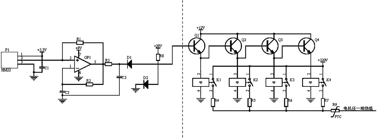
[0018] Embodiment 1, an air energy water heater power control circuit, including a pressure signal acquisition circuit and a step-by-step power control circuit, the pressure signal acquisition circuit collects the pressure signal after the air energy water heater compressor is heated and pressurized through in-phase amplification and clamping After the position is 0-20V, the pressure signal is used as the driving signal to control the conduction and cut-off of the triode of the step-by-step power regulation circuit;

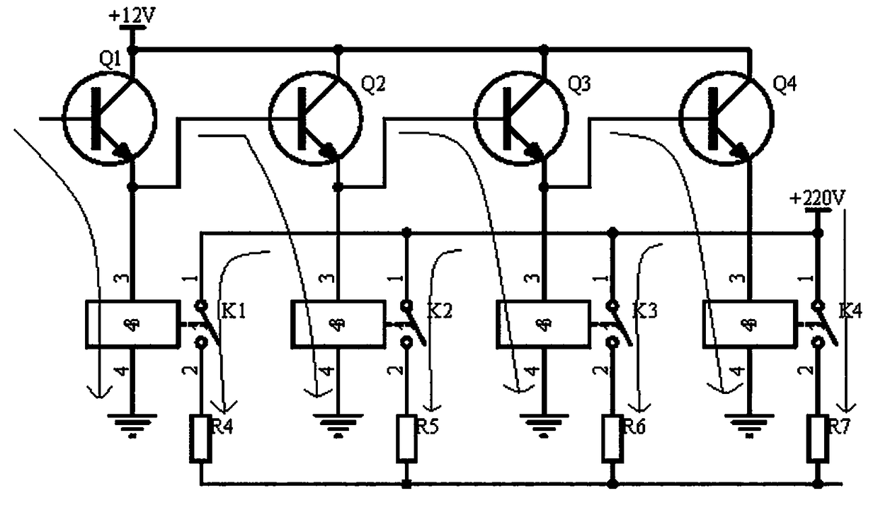
[0019] The step-by-step power control circuit uses triodes Q1-Q4 to control the power on and off of relays K1-K4, the base of the triodes Q1 is connected to the positive pole of the diode D2, the common terminal of the collectors of the triodes Q1-Q4 is connected to the power supply +12V, and the triodes Q1-Q4 The emitters of Q4 are respectively connected to contacts 3 of relays K1~K4, the emitter of transistor Q1 is connected to the base of transistor Q2, the emi...

Embodiment 2

[0020] Embodiment 2. On the basis of Embodiment 1, the pressure signal acquisition circuit adopts a pressure sensor P1 of model HM22. In order to allow the pressure signal collected by the pressure sensor P1 to be used as a driving signal to control the conduction and cut-off of the triodes Q1-Q4, Firstly, the op amp OP1 is positive-phase amplified, and the positive-phase amplified pressure signal is purely an abnormal signal. In order to protect the entire circuit, diodes D1, D2 and resistor R8 are designed to clamp the potential within 0~+20V. The pressure sensor P1 The power supply terminal is connected to the power supply +3.3V and one end of the capacitor C1, the ground terminal of the pressure sensor P1 and the other end of the capacitor C1 are grounded, and the output terminal of the pressure sensor P1 is connected to the positive input terminal of the op amp OP1 and the resistor R1 One end, the inverting input terminal of the operational amplifier OP1 is connected to on...


PUM


Abstract

The invention relates to a power regulating circuit of an air energy water heater. The circuit comprises a pressure signal collecting circuit and a step-by-step power regulating circuit. The pressure signal collecting circuit performs cophase amplification on a pressure signal of a compressor of the air energy water heater collected after temperature rise and pressure boost and the clamp is 0-20V, and the pressure signal as a driving signal controls on and off of audions of the step-by-step power regulating circuit, so that an effect of heating a water tank to a constant temperature is guaranteed, and the problem of potential safety hazard of the compressor as the power of the compressor is adjusted according to water temperature when the compressor of the air energy water heater is warmed and pressurized is solved. Audions Q1-Q4 are adopted to control on and off of relays K1-K4, step-by-step on and off of the relays K1-K4 is controlled by means of step-by-step conductivity of the audions Q1-Q4, strong electricity of the relays K1-K4 is controlled by weak currents of the audions Q1-Q4, resistors R4-R7 are differentiated step-by-step, and the power of motor in the compressor of the air energy water heater is regulated, and strong electricity is controlled by means of weak currents. The power regulating circuit is safe and reliable, and meanwhile, the power of the motor in the compressor is relatively stably regulated, so that the power regulating circuit of the air energy water heater has huge practical value and promotional value.

Description

technical field [0001] The invention relates to the technical field of circuits, in particular to a power regulation circuit for an air energy water heater. Background technique [0002] Air-energy water heaters are widely used by many companies and families due to their advantages of energy saving, environmental protection, and no pollution. Air-energy water heaters are mainly composed of a circulation system and refrigerant. Flowing through the heat absorber to absorb the low-temperature heat in the surrounding air, after absorbing the heat and evaporating, it will be transformed from a liquid state to a gaseous state, and the gaseous refrigerant will be compressed and boosted to convert the low-temperature heat absorbed in the air into high-temperature heat, and the heat will be released when flowing through the heat exchanger. The cold water is heated, and the refrigerant after heat release is converted from gaseous to liquid, and then enters the heat absorber again to a...

Claims


Application Information

Patent Timeline
Patent Type & Authority Patents(China)
IPC IPC(8): F04B49/06F24H9/20
CPCF04B49/06F24H9/2014
Inventor 郑桂绵
Owner 佛山市顺德区约利节能设备有限公司
Why Eureka
Try Eureka