
Combustor controlling method and combustor controlling system

A control method and burner technology, which is applied in the field of hazardous waste incineration treatment, can solve the problems of high labor intensity, difficulty in on-site adjustment, and shortened equipment life, so as to reduce material consumption, reduce labor intensity, and save operating costs. Effect

Active Publication Date: 2017-10-20
EVERBRIGHT ENVIRONMENTAL TECH CHINA CO LTD +3
View PDF6 Cites 0 Cited by
  • Summary
  • Abstract
  • Description
  • Claims
  • Application Information

AI Technical Summary

Problems solved by technology

However, because it only has two gears of high fire and low fire in actual use, it is difficult to adjust on-site, and the labor intensity of personnel is high, which requires continuous adjustment to meet the needs of working conditions; at the same time, it causes waste of fuel, shortened equipment life, and labor intensity of personnel. Big

Method used


Image

  • Combustor controlling method and combustor controlling system
  • Combustor controlling method and combustor controlling system
  • Combustor controlling method and combustor controlling system

Examples


Embodiment 1

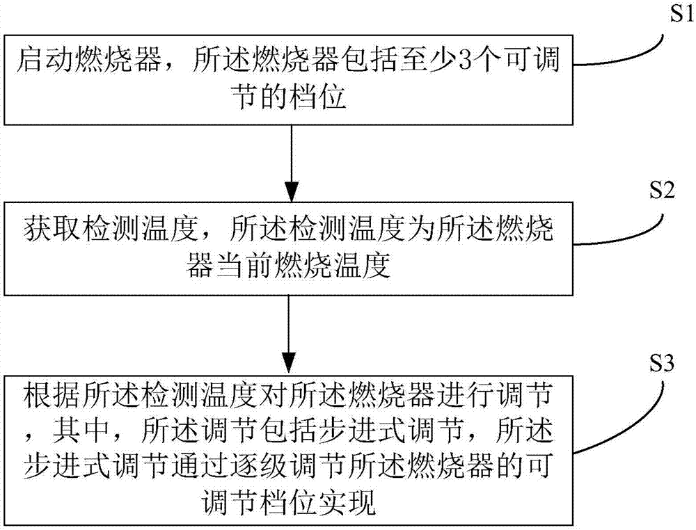
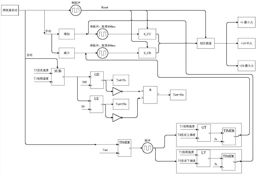
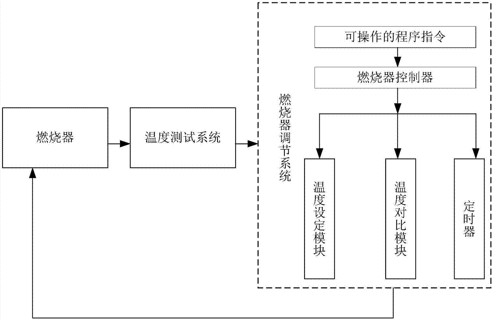
[0053] Refer below figure 1 , figure 2 and image 3 The burner control method of the present invention is schematically described, wherein figure 1 It is a schematic flowchart of a burner control method according to an embodiment of the present invention; figure 2 It is a schematic diagram of burner control in practical application according to the present invention; image 3It is a schematic diagram of a burner control system according to an embodiment of the present invention.

[0054] First, see figure 1 , execute step S1: start the burner, the burner includes at least 3 adjustable gears.

[0055] Exemplarily, the burner may be any burner including at least 3 adjustable gears. Exemplarily, the adjustable gear position of the burner can be realized by using a pulse width modulation controlled servo motor. Take a servo motor with a rated operating range of 90° and a rotation time of 12s for 90° as an example. Exemplarily, the servo motor is controlled by a pulse sig...

Embodiment 2

[0067] The present invention also provides a burner control system, see image 3 , shows a schematic diagram of a burner control system according to the present invention, the system includes: a burner, a temperature testing system and a burner adjustment system. The burner includes at least 3 adjustable gears. The burner including at least 3 adjustable gears can realize step-by-step adjustment of the burner, which can improve the load adjustment range of the burner, the utilization rate of fuel, reduce unnecessary material consumption and labor intensity, and improve The life of the equipment can save the operating cost of the enterprise and improve the efficiency. Exemplarily, the adjustable gear position of the burner can be realized by using a pulse width modulation controlled servo motor. Take a servo motor with a rated operating range of 90° and a rotation time of 12s for 90° as an example. Exemplarily, the servo motor is controlled by a pulse signal with a pulse widt...


PUM


Abstract

The invention provides a combustor controlling method and a combustor controlling system. The method comprises the following steps: starting a combustor including at least three adjustable gears; acquiring a detection temperature, wherein the detection temperature is a current combustion temperature of the combustor; adjusting the combustor according to the detection temperature, wherein the adjustment comprises stepping type adjustment which is realized by adjusting the adjustable gears of the combustor grade by grade. According to the combustor controlling method and the combustor controlling system disclosed by the invention, the stepping type adjustment of the combustor can be realized, a load adjustment range of the combustor can be improved, the utilization rate of fuels is improved, the unnecessary material consumption and labor intensity of personnel are reduced, the service life of the equipment is prolonged, the operation cost of enterprises is saved, and the efficiency is improved.

Description

technical field [0001] The invention relates to the field of hazardous waste incineration treatment, in particular to a burner control method and a burner control system. Background technique [0002] There are mainly two types of burners in the hazardous waste incineration treatment system, the start-up burner and the auxiliary burner. The main function of the start-up burner is that, on the one hand, it is used to evaporate the water of the refractory materials lining the rotary kiln, the second combustion chamber, the waste heat boiler, etc. according to the design temperature requirements to prevent the refractory materials from cracking; On the one hand, when starting the furnace in normal production, the temperature in the rotary kiln is raised to 850°C for feeding to ensure that the waste can be ignited normally. The main function of the auxiliary burner is to start in time when the temperature in the secondary combustion chamber is lower than 1000°C, to ensure that ...

Claims


Application Information

Patent Timeline
IPC IPC(8): F23N5/00
CPCF23N5/00F23N2225/16
Inventor 张二威蔡曙光陈涛杨仕桥朱福刚陈忠邵哲如王健生朱亮曹伟钱中华洪益州杨应永高秀荣张晓军
Owner EVERBRIGHT ENVIRONMENTAL TECH CHINA CO LTD
Learn More