Wearing influencing factor tester of yarn in porcelain eye position

A technology of influencing factors and testers, applied in the direction of testing wear resistance, using repetitive force/pulse force to test the strength of materials, instruments, etc., to achieve the effect of convenient operation and high test efficiency

Active Publication Date: 2017-10-20
HEBEI UNIVERSITY OF SCIENCE AND TECHNOLOGY
View PDF11 Cites 3 Cited by
  • Summary
  • Abstract
  • Description
  • Claims
  • Application Information

AI Technical Summary

Problems solved by technology

Therefore, the existing yarn abrasion testing instruments and methods are difficult to provide effective abrasion performance parameters for the latter

Method used


Image

  • Wearing influencing factor tester of yarn in porcelain eye position
  • Wearing influencing factor tester of yarn in porcelain eye position
  • Wearing influencing factor tester of yarn in porcelain eye position

Examples


Embodiment 1

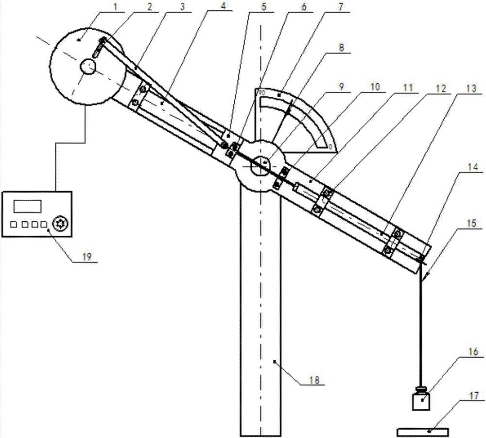
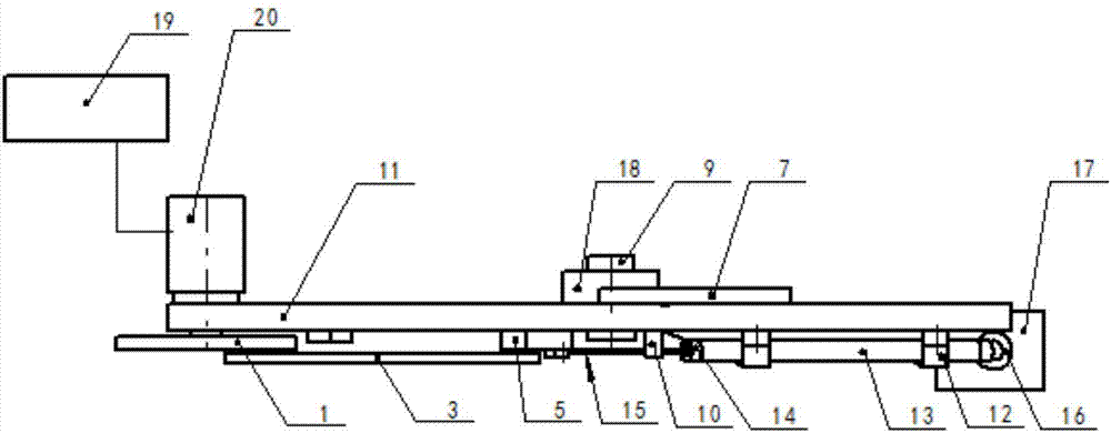
[0031] Embodiment 1: The yarn is fixed on the tester, and by changing the motor speed, the angle between the axis of the hollow tube and the yarn to be tested, and the weight of the weight, the number of revolutions of the motor when the yarn is broken under different conditions is recorded.

[0032] Step 1: Fix one end of the 3K carbon fiber multifilament to the upper end of the slider, pass through the hollow tube and connect with the weight. The aperture of the porcelain eye is 5mm, the yarn friction length is 5cm, and the material is ceramic.

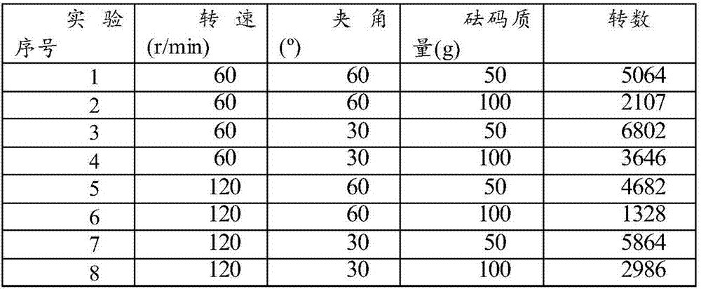
[0033] Step 2: Adjust the speed controller, the angle pointer and the weight of the weight. When the carbon fiber fracture occurs at the friction position with the porcelain eye, it is recorded as a valid sample, and record the number of revolutions on the display of the number of revolutions at this time. See Table 1.

[0034] Table 1 Friction performance test of 3K carbon fiber multifilament ceramic eye

[0035]

Embodiment 2

[0036] Embodiment 2: The yarn is fixed on the tester, the revolution control button is set, and the yarn wear resistance test is carried out by changing the motor speed, the angle between the hollow tube axis and the yarn to be tested, and the weight of the weight. After the yarn is rubbed, the yarn strength test is carried out, and the strength damage rate of the yarn is calculated.

[0037] Step 1: Fix one end of the 3K carbon fiber multifilament to the upper end of the slider, pass through the hollow tube and connect with the weight. The aperture of the porcelain eye is 5mm, the yarn friction length is 5cm, and the material is ceramic.

[0038] Step 2: Adjust the speed controller, angle pointer and weight weight, set the number of rotation control button to 100 rpm, and perform a strength test on the original carbon fiber multifilament and the sample after friction. The breaking strength of the original carbon fiber multifilament is 171N. The original carbon fiber multifil...


PUM

PropertyMeasurementUnit
pore sizeaaaaaaaaaa

Abstract

The invention relates to a wearing influencing factor tester of a yarn in a porcelain eye position. A swinging plate is hinged to the upper end of a vertical support, a track segment is arranged at one side of the front surface of the swinging plate, and a slide block runs on the track in a direction guiding manner; a hollow tube is coaxially fixedly arranged at the other side of the front surface of the swinging plate, and two ends of the hollow tube are provided with porcelain eyes; the end portion, at one side of the slide block, of the swinging plate is fixedly provided with a motor, the driving shaft of the motor drives a disc arranged on the front side of the swinging plate, one end of a swinging rod is hinged to the front disc surface of the disc, and the other end of the swinging rod is hinged to the slide block; and one end of a yarn to be detected is fixed on the slide block through a clamping plate, and the yarn to be detected traverses through the hollow tube and is hoisted with a counterweight. The tester has the advantages of convenience in operation, high test efficiency, test of the wearing influencing factor of the yarn passing through the porcelain eyes by regulating the speed of the motor, the angle between the yarn and the central axis of the porcelain eyes and the mass of the counterweight, and provision of guaranteeing for the onsite rapid detection of the wearing performance of the yarn.

Description

technical field [0001] The invention belongs to the field of textiles, and relates to textile performance testing equipment, in particular to a testing instrument for influencing factors of abrasion at yarn porcelain eyes. Background technique [0002] With the development of textile science and technology, whether it is in the processing of clothing textiles or industrial textiles, the requirements for yarns are getting higher and higher, especially for the wear resistance of yarns. Existing yarn wear performance testing devices include the Constant Tension Transport (CTT for short) yarn comprehensive quality evaluation system of the American Lawson company, the Y731 cohesion machine, the German ZweigleG522 yarn abrasion tester, and the domestic LFY-109 multi-functional Yarn Abrasion Tester, SHIRLEY-SDL Y027 Yarn Abrasion Tester, New Zealand Langz Research Institute (WRONZ) Yarn Abrasion Tester, etc. Most of these yarn abrasion performance testing instruments use the capst...

Claims


Application Information

Patent Timeline
Patent Type & Authority Applications(China)
IPC IPC(8): G01N3/56G01N3/34G01N3/38
CPCG01N3/34G01N3/38G01N3/56G01N2203/0688G01N2203/0676G01N2203/005G01N2203/0017G01N2203/0033G01N2203/0005G01N2203/028
Inventor 马晓红檀江涛石宝秦志刚
Owner HEBEI UNIVERSITY OF SCIENCE AND TECHNOLOGY
Why Eureka
Try Eureka