Overspeed electronic load system

An electronic load and control system technology, applied in the direction of power supply testing, measurement of electrical variables, improvement of basic electrical components, etc., can solve the problem that resistance boxes and electronic loads cannot meet requirements, cannot meet load switching speed requirements, and mechanical switch switching speed is slow. and other problems, to achieve the effect of fast switching speed, fast speed, and fast current response speed

Pending Publication Date: 2017-10-20
陕西晟思智能测控有限公司
View PDF2 Cites 6 Cited by
  • Summary
  • Abstract
  • Description
  • Claims
  • Application Information

AI Technical Summary

Problems solved by technology

Conventional resistance boxes and electronic loads can no longer meet the requirements
The main reason is that the switching speed of the mechanical switch of the resistance box is slow, and the contacts are sintered under high-frequency current, while the response speed of the traditional electronic load is slow, about 2.5A / uS, without pulse function, which cannot meet the current requirements of this item. 600A / uS current response speed and 150nS load switching speed requirements

Method used


Image

  • Overspeed electronic load system
  • Overspeed electronic load system
  • Overspeed electronic load system

Examples


Embodiment Construction

[0021] The implementation of the present invention will be described in detail below in conjunction with the accompanying drawings and examples, so as to fully understand and implement the process of how to apply technical means to solve technical problems and achieve technical effects in the present invention. It should be noted that, as long as there is no conflict, each embodiment and each feature in each embodiment of the present invention can be combined with each other, and the formed technical solutions are all within the protection scope of the present invention.

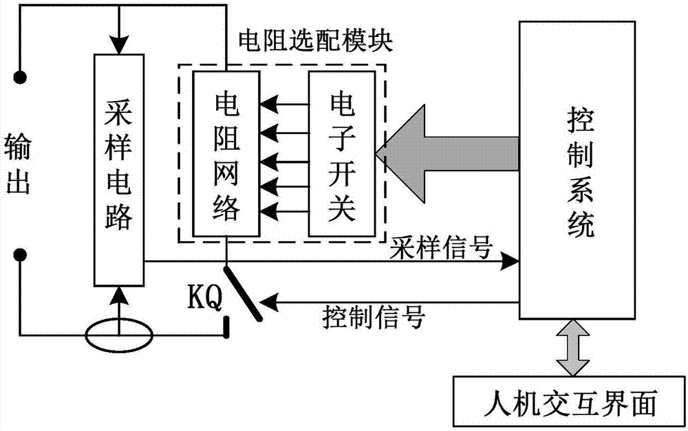
[0022] figure 1 It is a block diagram of the patented electronic load system of the present invention. As shown in the figure, an ultra-fast electronic load system mainly includes a human-computer interaction interface, a control system, a resistance matching module, a sampling circuit, and an output port. The human-computer interaction interface is connected with the control system, and transmits data betw...


PUM


Abstract

The invention discloses an overspeed electronic load system. The overspeed electronic load system comprises a man-machine interaction interface, a control system, a resistance matching module, a sampling circuit and an output port, wherein the resistance matching module comprises the resistance network and electronic switches, a resistance value is divided by the resistance matching module into different multiple value segments, each resistance value segment internally comprises multiple different resistance values and the electronic switches in parallel and series connection modes to carry out resistance value matching to form the resistance network, an output end of each resistance value segment outputs a resistance value through a relay switch to an output port of an electronic load, the man-machine interaction interface and the control system are connected and realize mutual data transmission, and an output end of the control system is connected with the resistance matching module and is used for controlling resistance matching of the resistance matching module.

Description

technical field [0001] The invention relates to the technical field of power electronics, in particular to an electronic load system. Background technique [0002] The load is the necessary equipment for power detection, which is used to detect the load capacity, response time, power quality and other indicators of the power supply. In applications with low requirements, a resistance box composed of passive components and mechanical switches is used as the load, which has simple functions and low price. In high-precision applications, most of the electronic loads are used as the detection load of the power supply. The electronic load has the characteristics of high precision, continuously adjustable load current or voltage, and complete functions. The relative price is relatively high, and the response time is generally in milliseconds. Performance test for DC power supply and power supply below intermediate frequency. [0003] For the current special power supply, such as...

Claims


Application Information

Patent Timeline
Patent Type & Authority Applications(China)
IPC IPC(8): G01R1/20G01R31/40
CPCG01R1/203G01R31/40
Inventor 张新涛刘钟佳吴强国陈磊
Owner 陕西晟思智能测控有限公司
Why Eureka
Try Eureka