Integrated electromechanical permanent magnet driving system
A permanent magnet drive and electromechanical technology, applied in the direction of electromechanical devices, electric components, magnetic circuit rotating parts, etc., can solve the problems of difficult braking, serious mechanical loss, high speed reduction ratio, etc., and achieve simple and convenient design and manufacture, simple and compact structure , the effect of increasing the braking torque
- Summary
- Abstract
- Description
- Claims
- Application Information
AI Technical Summary
Problems solved by technology
Method used
Image
Examples
Embodiment 1
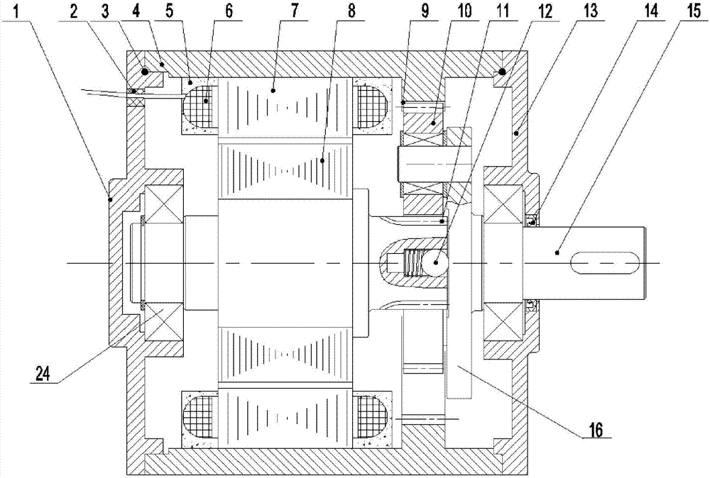
[0037] In this embodiment, a mechatronic permanent magnet drive system, such as figure 1 and Figure 4 As shown, it includes a casing, a winding stator core, a rotor core 8, a rotating shaft 11, a deceleration system, an output shaft 15, an acceleration system, a brake shaft 20 and a brake 22, and the above-mentioned winding stator core, rotor core 8, The rotating shaft 11, the deceleration system and the acceleration system are all arranged in the casing, and the above-mentioned brake 22 is installed on the outer side wall of the above-mentioned casing. As a specific implementation of this embodiment, the above-mentioned casing includes a left end cover 1, a casing 4 and a right end cover 13, and the above-mentioned left end cover 1 and right end cover 13 are respectively arranged on the left end and the right end of the above-mentioned cylindrical casing 4, and are passed through The screws are fixed. The winding stator core in this embodiment includes a stator core 7 and ...
Embodiment 2
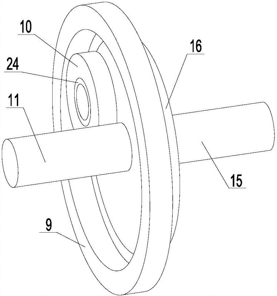
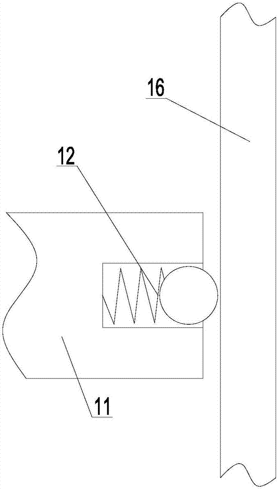
[0043] This embodiment is used as a kind of specific implementation manner of embodiment 1, such as figure 1 and figure 2 and Figure 4 As shown, in this embodiment, the above-mentioned deceleration system is defined to include a deceleration planetary gear 10, a deceleration ring gear 9, a deceleration planet carrier 16 and a transmission shaft. In this embodiment, the above-mentioned rotating shaft 11 is defined as a gear shaft. The right end is provided with a right external tooth to form a sun gear, and the deceleration planetary carrier 16 is defined as a disc. An internal gear A is provided on the inner wall of the above-mentioned deceleration ring gear 10, and the above-mentioned deceleration planetary gear is meshed and connected to the right external tooth. 10, and the deceleration planetary gear 10 is meshed and connected to the A internal teeth of the above-mentioned deceleration ring gear 10 at the same time. On the inner side wall, and limit that the above-ment...
Embodiment 3
[0046] This embodiment is further improved on the basis of embodiment 2, as Figure 4 and Figure 5 As shown, in this embodiment, the above-mentioned acceleration system is defined as a planetary acceleration system, which includes an acceleration planetary gear 18, an acceleration ring gear 19, an acceleration planetary carrier 17 and a synchronous transmission shaft. In this embodiment, the above-mentioned acceleration planetary carrier 17 is defined It is a disc, and the accelerating planet carrier 17 is vertically arranged on the left side of the above-mentioned rotating shaft 11 and is located on the right of the above-mentioned accelerating planetary gear 18, accelerating ring gear 19 and braking shaft 20, and the left end of the above-mentioned rotating shaft 11 is fixedly connected to the above-mentioned Accelerate the right end of the planetary carrier 17, when the above-mentioned rotating shaft 11 rotates, the above-mentioned accelerating planetary gear 18 will rotat...
PUM
 Abstract
Description
Claims
Application Information
 - R&D
- Intellectual Property
- Life Sciences
- Materials
- Tech Scout
- Unparalleled Data Quality
- Higher Quality Content
- 60% Fewer Hallucinations
Browse by: Latest US Patents, China's latest patents, Technical Efficacy Thesaurus, Application Domain, Technology Topic, Popular Technical Reports.
© 2025 PatSnap. All rights reserved.Legal|Privacy policy|Modern Slavery Act Transparency Statement|Sitemap|About US| Contact US: help@patsnap.com


