Eureka AIR delivers breakthrough ideas for toughest innovation challenges, trusted by R&D personnel around the world.

Millimeter wave high-speed frequency divider

A frequency divider, millimeter wave technology, applied in pulse counters, counting chain pulse counters, pulse counters using semiconductor devices, etc., can solve the problems of large area, wide frequency division range, inability to achieve, etc. The effect of a wide frequency range

Active Publication Date: 2017-10-20
江苏微远芯微系统技术有限公司
View PDF4 Cites 0 Cited by
  • Summary
  • Abstract
  • Description
  • Claims
  • Application Information

AI Technical Summary

Problems solved by technology

Due to the use of inductance and capacitance passive components, the area of ​​this circuit is large, and due to the high Q value characteristics of inductance and capacitance, traditional circuits cannot achieve a wide frequency division range

Method used


Image

  • Millimeter wave high-speed frequency divider
  • Millimeter wave high-speed frequency divider

Examples


Embodiment Construction

[0015] The technical solution of the present invention will be described in further detail below in conjunction with specific embodiments and accompanying drawings.

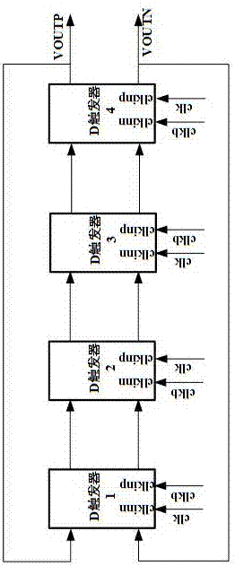
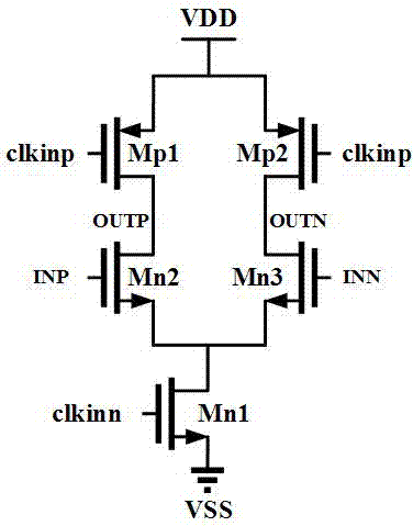
[0016] like figure 1 and figure 2 The shown millimeter-wave high-speed frequency divider includes a first D flip-flop, a second D flip-flop, a third D flip-flop and a fourth D flip-flop connected in sequence, and the output of the first D flip-flop The input end of the second D flip-flop is connected in series, the output end of the second D flip-flop is connected in series with the input end of the third D flip-flop, and the output end of the third D flip-flop is connected in series with the fourth D flip-flop The input end of the fourth D flip-flop is connected in series with the input end of the first D flip-flop; the first D flip-flop, the second D flip-flop, the third D flip-flop and the fourth D flip-flop The internal circuit structures all include a signal injection part and a signal transmission part, ...


PUM


Abstract

The invention discloses a millimeter wave high-speed frequency divider, and relates to the field of millimeter wave integrated circuits. The millimeter wave high-speed frequency divider is a frequency divider module applied in a millimeter wave transceiver chip, and solves the technical problems that the existing high-speed frequency divider is too large in area and too narrow in frequency division range. The millimeter wave high-speed frequency divider comprises four simple D triggers connected in sequence into a ring. The millimeter wave high-speed frequency divider not provided with passive devices such as an inductor occupying large area has the technical advantages of small area and large frequency division range.

Description

technical field [0001] The invention relates to the field of millimeter-wave integrated circuits, in particular to a millimeter-wave high-speed frequency divider, which is a frequency divider module used in millimeter-wave transceiver chips. Background technique [0002] Because the millimeter-wave frequency band has a high available bandwidth and high detection accuracy, millimeter-wave chips are widely used in wireless communication, radar, guidance, remote sensing technology, radio astronomy, and electronic countermeasures. In recent years, with the successive opening up of millimeter wave frequency bands, millimeter wave chips have become a hot spot. How to design a high-speed frequency divider with low power consumption, small area and large frequency division range has always been a subject worth studying. [0003] At present, the more common millimeter-wave high-speed frequency divider is an injection-locked frequency divider. In the injection-locked frequency divid...

Claims


Application Information

Patent Timeline
IPC IPC(8): H03K23/00H03K3/3562
CPCH03K3/3562H03K23/00H03K23/002
Inventor 田彤袁圣越赵辰丁博文陶李曹学坡沈叶东
Owner 江苏微远芯微系统技术有限公司
Why Eureka
Eureka Blog
Learn More