Power control method of electromagnetic heating device and cooking device

An electromagnetic heating device and power control technology, which is applied to the power control of electromagnetic heating devices and the field of cooking devices with electromagnetic heating, can solve the problems of long PWM signal turn-on time, high power tube back pressure, power tube breakdown, etc., to achieve Improve the power range, shorten the charge and discharge time, and reduce the effect of discharge back pressure value

Active Publication Date: 2017-10-20
HONGYANG HOME APPLIANCES
View PDF8 Cites 3 Cited by
  • Summary
  • Abstract
  • Description
  • Claims
  • Application Information

AI Technical Summary

Problems solved by technology

[0002] As a high-efficiency heating method, electromagnetic heating has penetrated into the field of kitchen appliances, but the current electromagnetic heating mainly adopts PWM signal drive for power control, and adjusts the power by adjusting the on-time of the PWM signal. For the convenience of control, usually Under the same power, the turn-on time of the PWM signal is consistent. When the power is high, due to the long turn-on time of the PWM signal, the back pressure of the power tube (IGBT) is high, which often causes the power tube to be broken down.
In addition, the electromagnetic heating device has many types of loads, and the back pressure generated by different loads is not the same. Some loads have too high back pressure, which will also cause the breakdown risk of the power tube.

Method used


Image

  • Power control method of electromagnetic heating device and cooking device
  • Power control method of electromagnetic heating device and cooking device
  • Power control method of electromagnetic heating device and cooking device

Examples


Embodiment approach 1

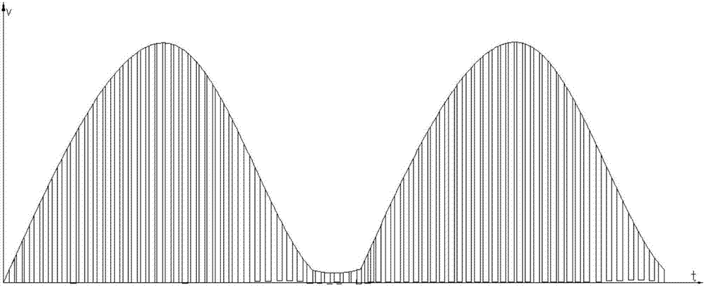
[0045] see Figure 5 , Image 6 As shown, the power control method of an electromagnetic heating device of the present invention, the electromagnetic heating device includes a coil, a power tube, an oscillating capacitor connected in parallel with the coil, a main control chip with a PWM signal output port, and a drive power tube to work The drive circuit, the PWM signal output port of the main control chip is connected to the drive circuit. When the power tube is in the working state, a voltage envelope is formed. This voltage envelope can be tested with an oscilloscope for easy observation.

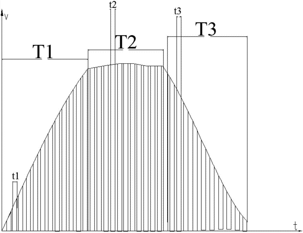
[0046] The main improvement of the control method of the present invention is that the main control chip divides the voltage envelope into three driving stages:

[0047] The first driving stage: the main control chip controls the conduction time of the PWM signal output to be t1;

[0048] The second driving stage: the main control chip controls the conduction time of the PWM signal ...

Embodiment approach 2

[0056] see Figure 7 , Figure 8 As shown, the second embodiment of the power control method of an electromagnetic heating device in the present invention differs from the first embodiment in that: the electromagnetic heating device also includes a zero-crossing detection circuit, and the main control chip obtains After the zero-crossing signal, enter the first driving stage.

[0057] In this embodiment, through the detection of the zero-crossing signal, the heating time of each stage can be accurately controlled, that is, the starting time is accurate, which effectively ensures the effective execution of each driving stage.

[0058] Other structures and beneficial effects of this embodiment are consistent with Embodiment 1 and will not be repeated here.

Embodiment approach 3

[0060] see Figure 9 , Figure 10 As shown, the third embodiment of the power control method of the electromagnetic heating device of the present invention is different from the first embodiment in that: the electromagnetic heating device also includes a back pressure detection circuit of the power tube, and the pre-set value in the main control chip Set the back-voltage limit value, if the back-voltage value acquired by the back-voltage detection circuit reaches the back-voltage limit value V0, the voltage envelope enters the second drive stage from the first driving stage, wherein the back-voltage limit value V0 is above 1kV. Specifically, the back-voltage limit value in this embodiment is between 1 kV and 1.3 kV, and the optimal value is 1.1 kV.

[0061] In this embodiment, the back pressure limit is used as the switching basis of the driving stage, instead of the time base of Embodiment 1, so that no matter what heating state the electromagnetic heating device is in, as l...


PUM


Abstract

The invention relates to a power control method of an electromagnetic heating device and a cooking device with electromagnetic heating. A main control chip is adopted to segment a voltage envelope into three driving stages, and PWM signal switching-on time in the three driving stages is modified, thereby greatly increasing the power range of electromagnetic heating, and preventing the problem of damage of a power tube in a heating process. Specifically, since a second driving stage in which PWM signal switching-on time is relatively short is set in the voltage envelope, charging and discharging time in an electromagnetic heating loop is shortened, thereby greatly reducing a value of discharging back pressure to which the power tube is subjected, and preventing the power tube from breakdown. And since charging and discharging time is short, the EMI performance is improved, and the performance of the whole device is further improved.

Description

technical field [0001] The invention relates to the field of kitchen appliances, in particular to a power control method of an electromagnetic heating device and a cooking device with electromagnetic heating. Background technique [0002] As a high-efficiency heating method, electromagnetic heating has penetrated into the field of kitchen appliances, but the current electromagnetic heating mainly adopts PWM signal drive for power control, and adjusts the power by adjusting the on-time of the PWM signal. For the convenience of control, usually Under the same power, the turn-on time of the PWM signal is consistent. When the power is high, the back pressure of the power tube (IGBT) is high due to the long turn-on time of the PWM signal, which often causes the power tube to be broken down. In addition, the electromagnetic heating device has many types of loads, and the back pressure generated by different loads is different. Some loads have too high back pressure, which will als...

Claims


Application Information

Patent Timeline
Patent Type & Authority Applications(China)
IPC IPC(8): H05B6/06
CPCH05B6/06
Inventor 朱泽春张伟
Owner HONGYANG HOME APPLIANCES
Why Eureka
Try Eureka