Air-energy two-stage heat pump air-conditioning system

A heat pump air conditioner and air energy technology, which is applied in air conditioning systems, space heating and ventilation, heating methods, etc., can solve problems such as air energy heat pumps not being able to provide normal heating, and achieve the effects of simple installation and maintenance, reduced energy consumption, and improved efficiency

Pending Publication Date: 2017-10-20
EVER SOURCE SCI & TECH DEV GRP CO LTD
View PDF5 Cites 10 Cited by
  • Summary
  • Abstract
  • Description
  • Claims
  • Application Information

AI Technical Summary

Problems solved by technology

[0004] The purpose of the present invention is to solve the problem that the air energy heat pump cannot provide normal heating under the condition of low ambient temperature, and provide an air energy two-stage heat pump air conditioning system with good heating effect, low price, energy saving, easy installation, and antifreeze

Method used


Image

  • Air-energy two-stage heat pump air-conditioning system
  • Air-energy two-stage heat pump air-conditioning system
  • Air-energy two-stage heat pump air-conditioning system

Examples


no. 1 example

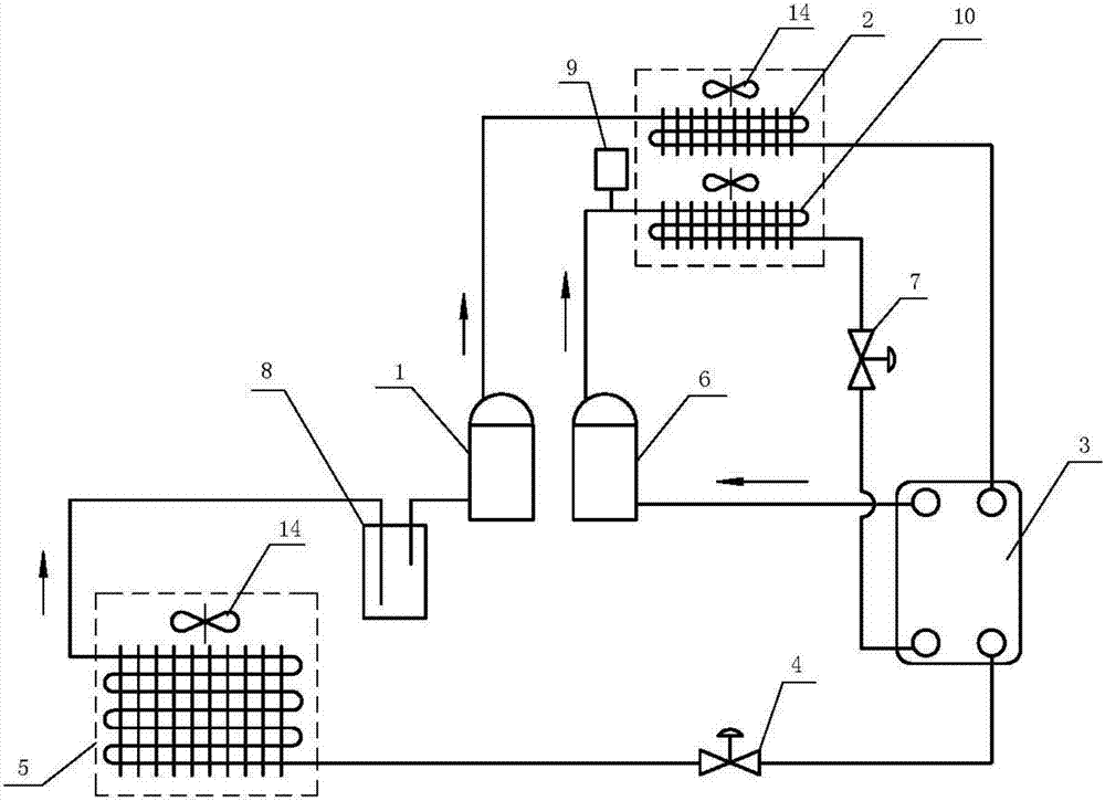
[0029] Such as figure 1 As shown, the air energy two-stage heat pump air conditioning system includes: outdoor low temperature evaporator 5, liquid storage tank 8, low temperature compressor 1, indoor low temperature condenser 2, heat exchanger 3, first expansion valve 4, high temperature compressor 6, Indoor high temperature condenser 10 and second expansion valve 7. The outdoor low-temperature evaporator 5, liquid storage tank 8, low-temperature compressor 1, indoor low-temperature condenser 2, the first circuit of the heat exchanger 3 and the first expansion valve 4 are sequentially connected to form the first circuit, and the high-temperature compressor 6 and the indoor high-temperature The condenser 10, the second expansion valve 7 and the second circuit of the heat exchanger 3 are connected in turn to form a second circuit, and a buffer tank 9 is also installed between the high-temperature compressor 6 and the indoor high-temperature condenser 10; an indoor low-temperatu...

no. 2 example

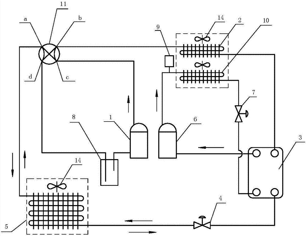
[0035] Such as figure 2 As shown, the second embodiment is basically the same as the first embodiment, the same parts will not be repeated, the difference is: between the outdoor low-temperature evaporator 5, the indoor low-temperature condenser 2, the low-temperature compressor 1 and the liquid storage tank 8 Equipped with a two-position four-way reversing valve 11, the a port of the two-position four-way reversing valve 11 is connected to the outlet of the outdoor low-temperature evaporator 5, and the b port of the two-position four-way reversing valve 11 is connected to the outlet of the indoor low-temperature condenser 2 The inlet is connected, the c port of the two-position four-way reversing valve 11 is connected with the outlet of the cryogenic compressor 1 , and the d-port of the two-position four-way reversing valve 11 is connected with the liquid storage tank 8 . The low-temperature compressor 1, the c port of the two-position four-way reversing valve 11, the b port...

no. 3 example

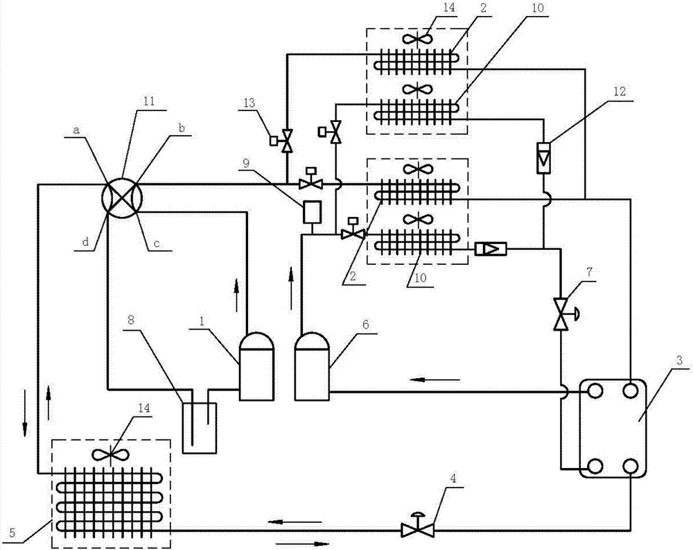
[0040] Such as image 3 As shown, the third embodiment is substantially the same as the second embodiment. The difference is that there are two sets of indoor condensers. That is, there are two indoor high-temperature condensers 10 and two indoor low-temperature condensers 2 respectively, the two indoor high-temperature condensers 10 are connected in parallel, and the two indoor low-temperature condensers 2 are connected in parallel. This embodiment can realize heating to two rooms at the same time. An electromagnetic valve 13 is installed between the two indoor low-temperature condensers 2 and the port b of the two-position four-way reversing valve 11, and an electromagnetic valve 13 is respectively installed between the two indoor high-temperature condensers 10 and the high-temperature compressor 6. Valve 13, a one-way valve 12 is installed between the two indoor high-temperature condensers 10 and the second expansion valve 7 respectively.

[0041] The heating and cooling...


PUM


Abstract

An air-energy two-stage heat pump air-conditioning system comprises first loop which is formed by an outdoor low temperature evaporator (5), a liquid storage tank (8), a low temperature compressor (1), an indoor low temperature condenser (2), a first path of a heat exchanger (3) and a first expansion valve (4) sequentially connected to each other, and a second loop which is formed by a high temperature compressor (6), an indoor high temperature condenser (10), a second expansion valve (7) and a second path of the heat exchanger (3) sequentially connected to each other. A buffer tank (9) is arranged between the high temperature compressor (6) and the indoor high temperature condenser (10), and an indoor low temperature condenser (2) and an indoor high temperature condenser (6) forms an indoor condenser set. The air-energy two-stage heat pump air-conditioning system consumes air energy to supply heat for a room in winter and cools a room in summer after installing a two-position four-way valve. The air-energy two-stage heat pump air-conditioning system has the advantages of high efficiency, easy installation and easy use. No water is used and freezing is not a problem, so that the system is more secure and reliable.

Description

technical field [0001] The invention relates to a heat pump system for residential or district heating, in particular to a heat pump air conditioning system utilizing air energy. Background technique [0002] At present, in cold regions or severe cold regions, most of the self-heating methods in rural areas are soil kang burning wood and soil heating coal. The traditional combustion heating method has high indoor temperature and poor overall comfort. Smoky environment pollution is serious. There are also users who use gas-fired wall-hung boilers for heating in urban residential quarters, but the world's natural gas resources are in short supply, and the burning of a large amount of natural gas also brings about environmental pollution. In areas with hot summer and cold winter, such as the middle and lower reaches of the Yangtze River in China, South China and Southwest China, most users use ordinary split air conditioners for heating. [0003] The low-temperature air-sourc...

Claims


Application Information

Patent Timeline
Patent Type & Authority Applications(China)
IPC IPC(8): F24F5/00F25B6/02F25B41/04F25B43/00F25B39/02F25B31/00F25B41/20
CPCF24F5/001F25B6/02F25B31/00F25B39/02F25B43/006F25B2339/02F25B2400/06F25B2500/31F25B2600/25F25B41/26F25B7/00F25B29/00
Inventor 徐生恒
Owner EVER SOURCE SCI & TECH DEV GRP CO LTD
Why Eureka
Try Eureka