Filter frame used for conventional chip cleaner

A chip conveyor, conventional technology, applied in the direction of metal processing machinery parts, maintenance and safety accessories, metal processing equipment, etc., to achieve excellent filtering effect, high filtering precision, and solve the effect of low filtering precision

Inactive Publication Date: 2017-10-24
NINGXIA KOCEL MACHINE TOOL ACCESSORIES
View PDF7 Cites 3 Cited by
  • Summary
  • Abstract
  • Description
  • Claims
  • Application Information

AI Technical Summary

Problems solved by technology

[0005] The purpose of the present invention is to provide a filter frame for a conventional filter chip conveyor in view of the above existing problems, so that the chip conveyor can obtain a high coolant flow rate and a relatively high cooling rate while ensuring the filtering effect. Good filtering effect to solve the deficiencies and defects of the existing technology

Method used


Image

  • Filter frame used for conventional chip cleaner
  • Filter frame used for conventional chip cleaner
  • Filter frame used for conventional chip cleaner

Examples


Embodiment 1

[0029] Example 1, such as Figure 1-6 Shown:

[0030] A filter frame for a conventional chip conveyor, comprising at least one filter frame 3 and at least one filter screen plate 8 with a thickness of 0.5mm-0.6mm; the filter screen plate 8 is matched and installed in the filter frame 3, and the filter screen A number of filter holes are arranged on the plate 8, and the filter holes are formed by array etching by photolithography or chemical milling, and the filter screen plate 8 includes an opening upper part 9 and an opening lower part 10; the structure of the filter holes includes a single cone structure, Straight pore structure and double-cone pore structure, wherein the double-cone pore structure includes an upper filter hole and a lower filter hole, the upper filter hole is located at the upper part 9 of the opening, the lower filter hole is located at the lower part 10 of the opening, and the upper filter hole and the lower filter hole The large ends of the tapered hole...

Embodiment 2

[0043] Example 2, such as Figure 1-6 Shown:

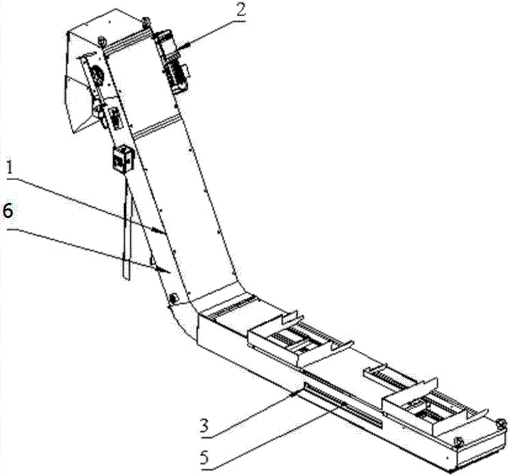
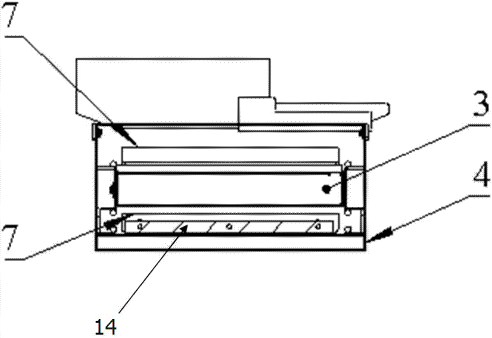
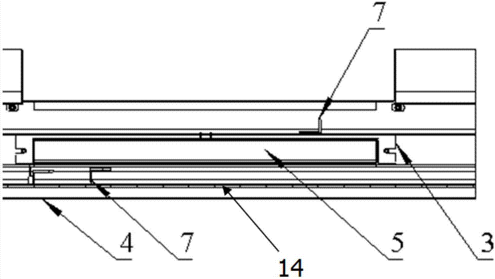
[0044] figure 1 It is an axonometric view of the chip conveyor body 1 of the present invention. In the figure, 3 is a filter frame. The chip conveyor body 1 also includes a liquid outlet 5, and the liquid outlet 5 conveys the cutting fluid filtered by the filter frame 3. exist figure 2 In , it is shown that a filter frame 3 is arranged inside the chain 14, that is, between the upper part and the lower part of the chain 14, for filtering cutting fluid. By placing the filter frame 3 inside the chain 14, the filter frame 3 is protected from large chips. There can be one or more filter frames 3 connected to the same chip conveyor inside the chip conveyor body 1, and the number of filter frames is determined according to the required flow rate, the amount of cutting fluid used and the frequency of cleaning. For example, if a large amount of cutting fluid is required, the number and size of filter frames 3 should be increased. The...


PUM


Abstract

The invention relates to the field of chip removal equipment, in particular to a filter frame used for a conventional chip cleaner. The filter frame comprises at least one filter frame body and at least one filter screen plate. The filter screen plates are mounted in the filter frame bodies in a matched mode and provided with a plurality of filter holes. A fluid outlet used for discharging filtered fluid is formed in one side of each filter frame body. A jet flushing system is arranged in each filter frame body and comprises a plurality of jet pipelines and jet nozzles arranged on the jet pipelines, wherein the end, extending out of the corresponding filter frame body, of one jet pipeline is provided with a connecting element. Scraping plates used for scraping and removing waste chips are arranged on the upper portion and the lower portion of each filter frame body correspondingly. The filter holes structurally comprise single-cone hole structures, straight hole structures and bicone hole structures, wherein each bicone hole structure comprises an upper filter hole and a lower filter hole, and cone hole small ends between the upper filter hole and the lower filter hole communicate with each other. A chain is mounted in a chip removal barrel of the chip cleaner, and the scraping plates are detachably and fixedly mounted on the chain. The filter frame is good in filter effect and has good practical value, and the waste chips are conveniently removed.

Description

technical field [0001] The invention relates to the field of chip removal equipment, in particular to a filter frame for a conventional chip remover, which is mainly used to effectively handle the chips generated by the conventional chip remover during machine tool work; more specifically, the filter frame is used for separating And filter chips and coolant generated during the use of machine tools. Background technique [0002] Usually, the chips generated by the machine tool during the machining process will be mixed with the cutting fluid and enter the chip conveyor. Because the cutting fluid of the machine tool is recycled, the chips mixed in the cutting fluid must be removed during the chip removal process. . Currently in the chip conveyor industry, conventional chain plate chip conveyors are widely used because of their ability to convey chips of any shape or size. However, due to structural and cost factors, the conventional chain plate chip conveyor has an obvious ...

Claims


Application Information

Patent Timeline
Patent Type & Authority Applications(China)
IPC IPC(8): B23Q11/00
CPCB23Q11/0042Y02P70/10
Inventor 王林焱何国峰马同堂赵敬王芬
Owner NINGXIA KOCEL MACHINE TOOL ACCESSORIES
Why Eureka
Try Eureka