Membrane bioreactor

A technology of membrane bioreactor and membrane filament, which is applied in biological treatment devices, sustainable biological treatment, biological water/sewage treatment, etc., can solve the problems of high requirements for equipment and technical personnel, complex and large equipment, and limited cleaning effect. Achieve the effects of good membrane pollution prevention and control, high membrane flux, and energy saving of fans

Pending Publication Date: 2017-10-24
广东力达环境技术有限公司
View PDF12 Cites 0 Cited by
  • Summary
  • Abstract
  • Description
  • Claims
  • Application Information

AI Technical Summary

Problems solved by technology

[0013] This method enhances the cleaning effect of the membrane surface by increasing the turbulent intensity of the liquid flow, and is effective in slowing down the deposition of pollutants on the membrane surface and improving the cleaning efficiency. The cleaning effect is limited when the ratio is unlikely to be too large
[0014] In addition, in the existing MBR, there are generally the following defects: a. The bottom aeration system needs to be designed separately, the equipment is complex and huge, and the cost is high; b. c. Glue is directly pasted after the membrane filaments are bundled, causing the membrane filaments to fall off from the membrane structure due to long-term left and right swings during operation; d. The fan energy consumption is high when the aeration system uses the fan to stir; e. The maintenance process is complex and requires high equipment and technical personnel

Method used


Image

  • Membrane bioreactor
  • Membrane bioreactor
  • Membrane bioreactor

Examples


Embodiment Construction

[0040]The following will clearly and completely describe the technical solutions in the embodiments of the present invention with reference to the accompanying drawings in the embodiments of the present invention. Obviously, the described embodiments are only some, not all, embodiments of the present invention. Based on the embodiments of the present invention, all other embodiments obtained by persons of ordinary skill in the art without creative efforts fall within the protection scope of the present invention.

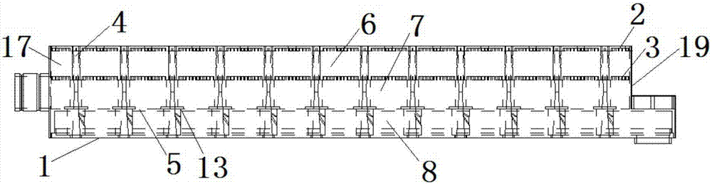
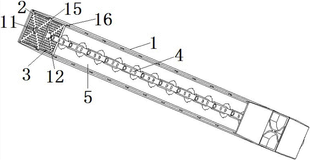
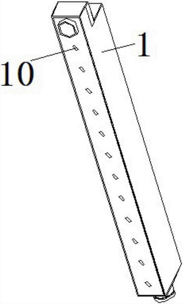
[0041] Such as Figure 1 to Figure 8 As shown, the preferred embodiment of the present invention is a membrane bioreactor, which includes a membrane filament and an aeration device, the membrane filament has a hollow channel, one end of which is closed, and the other end is open, and the aeration device is connected to the The open end of the membrane filament.

[0042] The aeration device includes a casing 1 with an open upper end, a first screen plate 2 , a secon...


PUM


Abstract

The invention provides a membrane bioreactor which comprises membrane wires, a shell, a first filter screen plate, a second filter screen plate and a plurality of aeration components. An opening is formed in the upper end of the shell. A shell cavity is divided into an upper cavity and a lower cavity by a partition plate in the shell, the first filter screen plate and the second filter screen plate arranged in the upper cavity at intervals, the cavity between the first filter screen plate and the second filter screen plate serves as a glue injection layer, the cavity between the second filter screen plate and the partition plate serves as a water outlet layer, the lower cavity serves as an air inlet layer, a plurality of screen holes are uniformly formed in the first filter screen plate and the second filter screen plate at intervals, the membrane wires penetrate the screen holes, the aeration components are uniformly arranged at the inner center of the shell at intervals and sequentially penetrate the air inlet layer, the water outlet layer and the glue injection layer from bottom to top, air inlet holes are formed in the aeration components in the air inlet layer, and opening ends of the membrane wires sequentially penetrate the screen holes and extend into the water outlet layer. The membrane bioreactor has the advantages of simple structure, low manufacturing cost and operating cost, high membrane flux and good membrane pollution control effect.

Description

technical field [0001] The invention relates to sewage treatment equipment, more specifically, to a membrane bioreactor. Background technique [0002] In recent years, the application of membrane technology in the field of sewage treatment, especially the membrane bioreactor (Membrane Bioreactor, referred to as MBR) process combined with bioreactors, as a new type of high-efficiency sewage treatment process, has received increasing attention. MBR is a new type of water treatment technology that combines a membrane separation unit and a biological treatment unit. It replaces the secondary settling tank with a membrane module to maintain a high concentration of active sludge in the bioreactor to reduce the footprint of sewage treatment facilities, and by keeping it low Sludge loading reduces the amount of sludge. The MBR process has the advantages of simple operation, separation of hydraulic retention time (HRT) and sludge age (SRT), high sludge concentration, strong impact l...

Claims


Application Information

Patent Timeline
IPC IPC(8): C02F3/12C02F3/20C02F3/34
CPCC02F3/1268C02F3/201C02F3/34C02F2203/006C02F2303/16Y02W10/10
Inventor 周丁熙周倩仪
Owner 广东力达环境技术有限公司
Why Eureka
Try Eureka