Offshore self-propelled rush-installed wellhead operator

A self-propelled and operational technology, applied in isolation devices, wellbore/well components, earthwork drilling and mining, etc., can solve the problems of fierce fire, strong heat radiation, unsafe hidden dangers, etc., so as to ensure the safety of equipment operation and improve mechanization degree, the effect of improving the overall performance

Active Publication Date: 2019-04-23
CHINA NAT OFFSHORE OIL CORP +1
View PDF9 Cites 0 Cited by
  • Summary
  • Abstract
  • Description
  • Claims
  • Application Information

AI Technical Summary

Problems solved by technology

[0002] During the drilling of offshore oil and natural gas, once an oil and gas well blows out and catches fire, especially when a gas well with high hydrogen sulfide content catches fire, the original wellhead control device will be severely damaged. In order to protect the ecological environment, reduce environmental pollution and reduce life If the fire is put out first, the crude oil or natural gas with hydrogen sulfide emitted from the well will cause serious pollution to the environment. For this reason , developed a self-propelled offshore wellhead operator
The existing technical problem is: when installing a new wellhead with the current rush-installed wellhead operating device with fire, the staff needs to operate at close range at the burning wellhead. Due to the high temperature of the burning wellhead, especially for natural gas wells containing hydrogen sulfide, the wellhead The temperature is high, the fire is fierce, and the heat radiation is strong, which has a great impact on the mechanical properties of the components of the emergency installation device; the requirements for the structural performance and high temperature protection of the emergency installation device are extremely high, and there are hidden dangers; the safety of emergency personnel cannot be guaranteed

Method used


Image

  • Offshore self-propelled rush-installed wellhead operator
  • Offshore self-propelled rush-installed wellhead operator
  • Offshore self-propelled rush-installed wellhead operator

Examples


Embodiment Construction

[0019] The present invention will be described in detail below in conjunction with the accompanying drawings and embodiments.

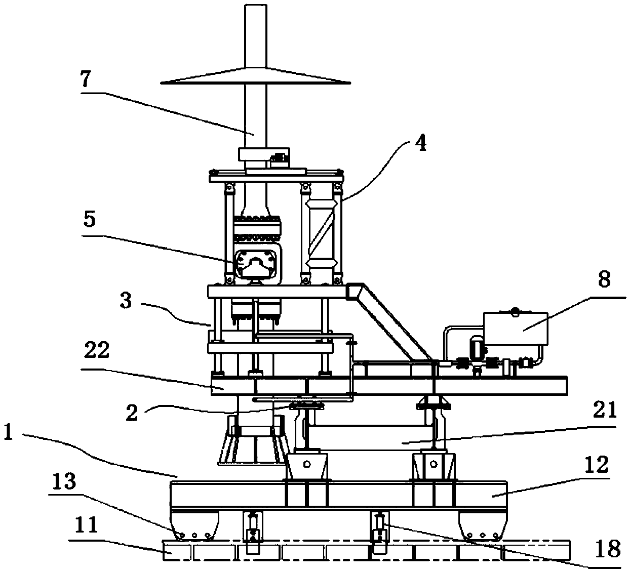
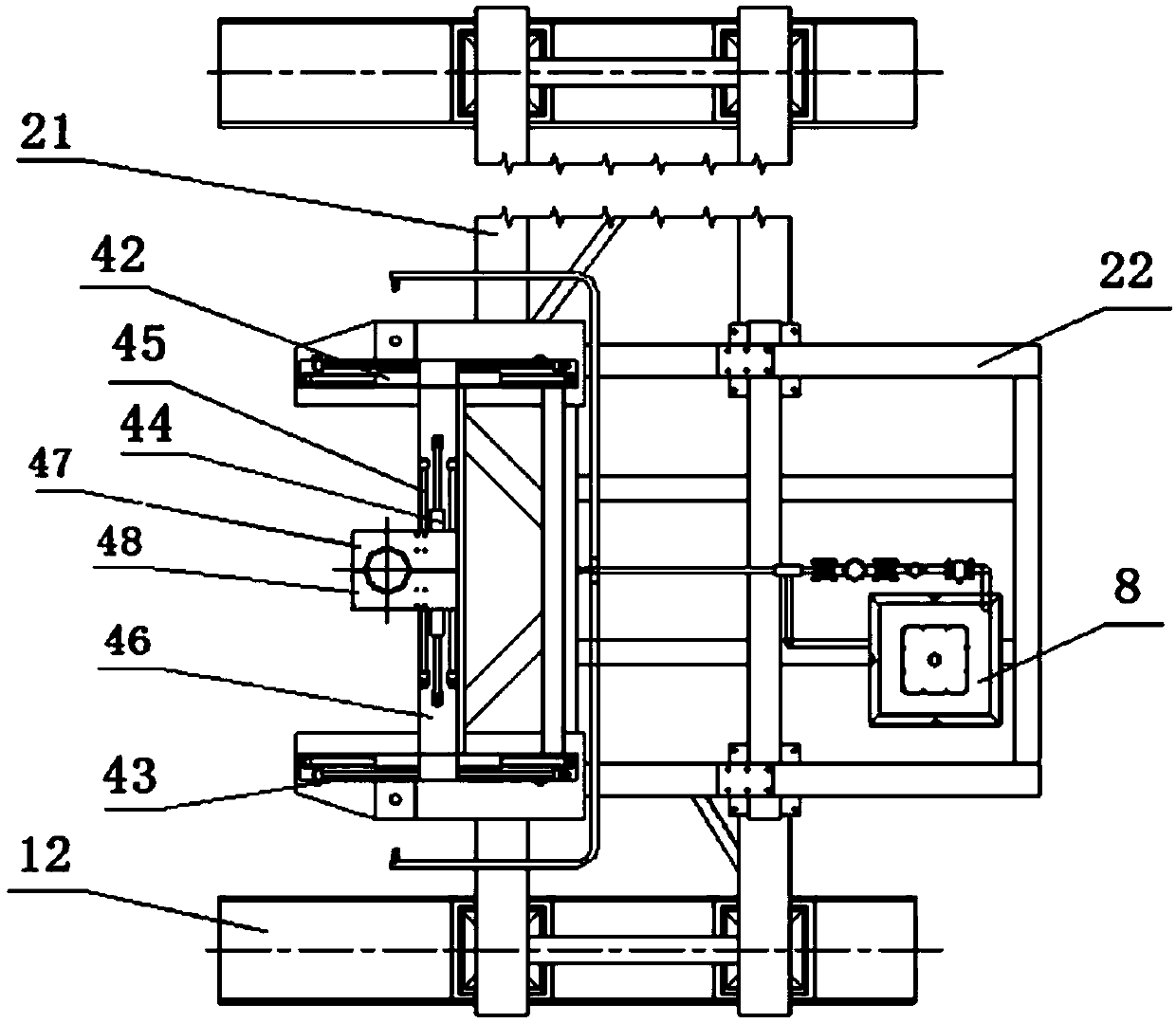
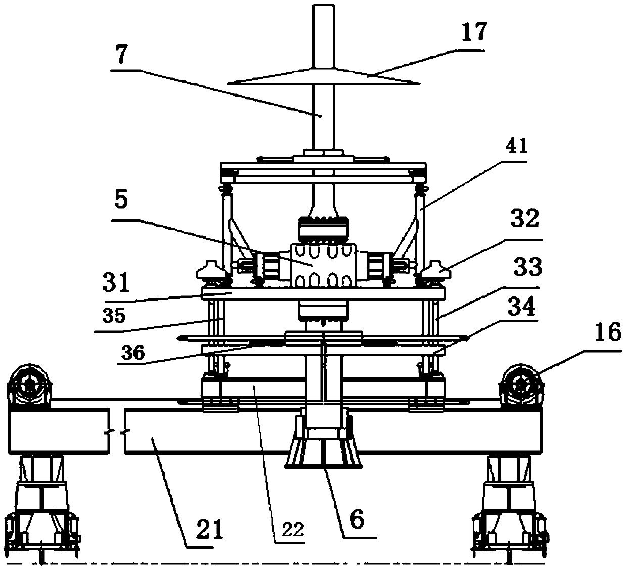
[0020] Such as Figure 1~4 As shown, the present invention provides a self-propelled offshore wellhead operation device, which includes a sliding system, a wellhead centering mechanism and a cooling system;

[0021] The sliding system includes an X-direction sliding system 1 and a Y-direction sliding system 2. The X-direction sliding system 1 includes a platform slide rail 11, a sliding leg 12 and a sliding mechanism 13. The platform slide rails located on both sides of the wellhead 11 are provided with sliding legs 12 respectively, and the sliding legs 12 are slidably connected to the platform slide rail 11 through the sliding mechanism 13; the Y-direction sliding system 2 includes a support 21 and a base 22, and the support 21 overlaps the On the sliding leg 12, the base 22 slides along the length direction of the support 21 and is connected above ...


PUM


Abstract

The invention discloses a maritime self-propelled wellhead installing operation device. The maritime self-propelled wellhead installing operation device is characterized by comprises sliding systems, a wellhead centering mechanism and a cooling system; the sliding systems comprise the X-direction sliding system and the Y-direction sliding system. The X-direction sliding system comprising platform sliding rails and two sliding supporting legs slidably connected to the platform sliding rails on two sides of a wellhead correspondingly through sliding mechanisms. The Y-direction sliding system comprises a supporting seat connected to the two sliding supporting legs in a lapping mode and a base slidably connected to the upper portion of the supporting seat in the length direction of the supporting seat. The wellhead centering mechanism comprises a bottom lifting system, a top adjusting device, a new wellhead, a centering bell mouth and an ignition cylinder. The cooling system comprises a water tank, a ball valve, a water pump, a cooling water pipeline and a spraying nozzle.

Description

technical field [0001] The invention relates to an offshore self-propelled emergency installation wellhead operating device, which belongs to the technical field of equipment manufacturing for offshore oil and gas well blowout out of control fire and fire emergency installation of new wellheads. Background technique [0002] During the drilling of offshore oil and natural gas, once an oil and gas well blows out and catches fire, especially when a gas well with high hydrogen sulfide content catches fire, the original wellhead control device will be severely damaged. In order to protect the ecological environment, reduce environmental pollution and reduce life If the fire is put out first, the crude oil or natural gas with hydrogen sulfide emitted from the well will cause serious pollution to the environment. For this reason , developed a self-propelled offshore wellhead operator. The existing technical problem is: when installing a new wellhead with the current rush-installe...

Claims


Application Information

Patent Timeline
Patent Type & Authority Patents(China)
IPC IPC(8): E21B36/00E21B35/00
CPCE21B35/00E21B36/001E21B36/003
Inventor 刘书杰周建良杨向前吴怡焦金刚岳家平殷志明
Owner CHINA NAT OFFSHORE OIL CORP
Why Eureka
Try Eureka