
A kind of oil well intelligent control method and device

An intelligent control and oil well technology, which is applied in earthwork drilling, wellbore/well components, measurement, etc., can solve problems that affect enterprise benefits, reduce oil pumping production, and large starting current, so as to improve safety and service life, Improve oil production efficiency and reduce impact force

Active Publication Date: 2020-12-15
温州南冠机械有限公司
View PDF7 Cites 0 Cited by
  • Summary
  • Abstract
  • Description
  • Claims
  • Application Information

AI Technical Summary

Problems solved by technology

[0004] In addition, when the existing sucker rod stops working, it usually stops at the lowest point of the sucker rod movement, which will have the following defects: (1) Once the sucker rod starts to work again, the sucker rod will move upward first, and the sucker rod will move upwards. The counterweight of the rod in the well is relatively large, and when the sucker rod moves upward, it must overcome a certain gravity, which requires the motor to generate a large starting current at the moment of starting.
However, on the one hand, the large starting current will cause the motor winding to heat up and the insulation will age, thereby shortening the service life of the motor; on the other hand, it will cause fluctuations in the grid voltage, which will affect the normal operation of other equipment connected to the grid; (2) When the sucker rod moves upward, it is easy to cause the sucker rod to break, which greatly wastes the cost; (3) The sucker rod moves upward first, which will prolong the pumping time, reduce the work efficiency, and then reduce the pumping output, which will affect the profit of the enterprise

Method used


Image

  • A kind of oil well intelligent control method and device
  • A kind of oil well intelligent control method and device
  • A kind of oil well intelligent control method and device

Examples


Embodiment Construction

[0045] The present invention will be further described in detail below in conjunction with the accompanying drawings and specific embodiments.

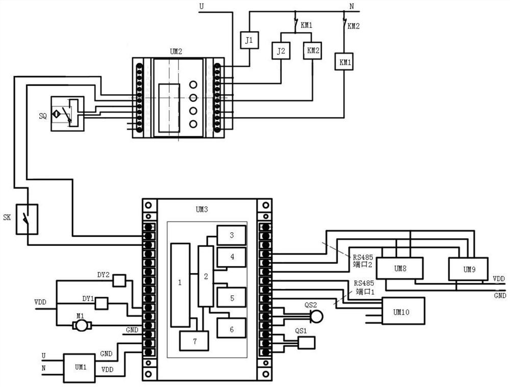
[0046] Such as figure 1 Shown: an oil well intelligent control device, including micro-sound sensor QS2, pressure transmitter QS1, wellhead sounding device and main controller UM7; micro-sound sensor QS2 and pressure transmitter QS1 are connected to the input end of the main controller UM7, The wellhead sounding device is connected to the output end of the main controller UM7.

[0047] Specifically, in order to know the position of the oil level, this embodiment introduces the micro-sound sensor QS2. Its detection principle is: by making a sound at the wellhead, the sound is transmitted to the oil level along the casing, and the sound bounces and travels along the casing. The pipe returns to the wellhead, and the sound wave signal is received at the wellhead to obtain the time traveled by the sound, and the depth of the oil level fro...


PUM


Abstract

An intelligent oil well control method and device, the control method comprising: step 1: setting the depth of the oil surface; step 2: detecting the casing pressure in the oil well, and if there is casing pressure in the well, controlling the gas in the oil well casing to release gas outside the well Make sound, get the depth of the oil level according to the speed of sound and time difference; if no casing pressure is detected in the casing of the oil well, pressurize the gas in the casing outside the well into the gas storage cylinder, then inject gas into the casing of the oil well to make sound, and then get the oil The depth of the oil surface; step 3: compare the actual measured oil surface depth with the set oil surface depth, and determine whether to pump oil according to the error value of the two. The invention also includes an intelligent oil well control device. On the one hand, the present invention can make full use of the pressure difference in the oil well to accurately obtain the specific position of the oil level, and improve oil production efficiency through intelligence; The safety and service life of the start-up when the oil motor is used.

Description

technical field [0001] The invention relates to the technical field of oil field pumping, in particular to an intelligent control method and device for an oil well. Background technique [0002] Sucker rod is an important part of rod pumping equipment. The sucker rod is generally connected into a sucker rod string through a coupling, the upper part is connected to the pumping unit through the polished rod, and the lower part is connected to the plunger of the oil well pump. . When the pumping unit is working, the motor drives the donkey head of the beam to reciprocate, and then the donkey head drives the polished rod and the sucker rod to reciprocate linearly up and down, and then transmits this movement to the piston in the downhole oil pump through the sucker rod . [0003] Before the sucker rod pumps oil, it is necessary to know the position of the oil level in the well. When controlling the oil level to recover oil, if the oil level is too deep, it will not be easy to...

Claims


Application Information

Patent Timeline
Patent Type & Authority Patents(China)
IPC IPC(8): E21B47/047E21B47/06E21B47/16E21B47/009
CPCE21B47/06E21B47/16E21B47/009E21B47/047
Inventor 李秀才戴晓洪
Owner 温州南冠机械有限公司
Learn More