Simulated candle lamp

A technology for simulating candles and candle wicks, which is applied in the field of candle lamps and simulated candle lamps. It can solve the problems of high power consumption, short continuous use time, and poor simulation effect, and achieve low energy consumption, long use time, and high simulation degree. Effect

Inactive Publication Date: 2017-10-24
陈善长 +3
View PDF8 Cites 3 Cited by
  • Summary
  • Abstract
  • Description
  • Claims
  • Application Information

AI Technical Summary

Problems solved by technology

However, this kind of wick simulation structure still has many defects, as follows: 1. These structures can only simulate the effect of the candle wick swinging with the wind, but cannot simulate the burning and beating effect of the candle flame in a windless state; 2. Because the simulated flame swings freely with the wind, the swing range and direction of the candle chip are random and uncontrollable. Therefore, it is necessary to reserve a large swing space for the lower end of the candle chip, and the diameter of the candlestick needs to be enlarged. This structure It cannot be used to simulate small-diameter candles; 3. Candle lamps are generally powered by batteries, and their voltage is low, so the frequency of electromagnet-driven candle chip swings is slow, and the flame part of the candle chip can see a clear edge outline, without the periphery of the candle flame 4. The flame highlight area of ​​the candle chip is simulated by the reflected light from the center of the flame sheet irradiated by the LED light, but the position of the light will not change, while the candle chip swings randomly and greatly , which will make the highlighted area of ​​the flame constantly deviate from the center of the candle chip, and the simulation effect is poor; Short duration of use

Method used


Image

  • Simulated candle lamp
  • Simulated candle lamp
  • Simulated candle lamp

Examples


Embodiment Construction

[0023] The present invention will be further described below in conjunction with accompanying drawing:

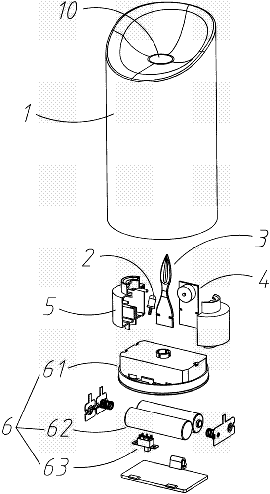
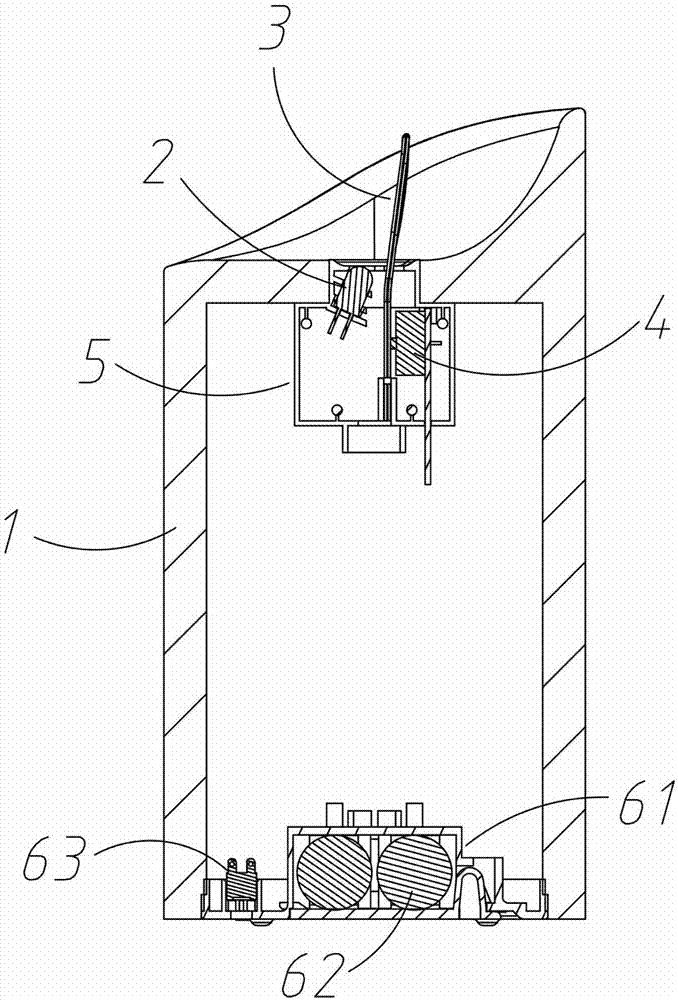
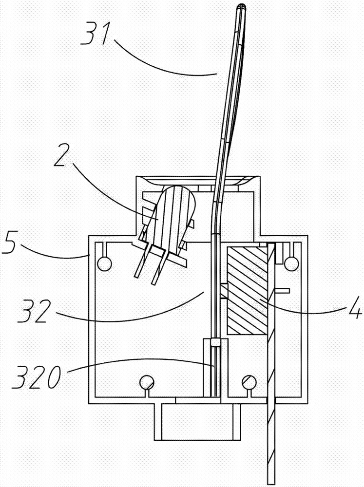
[0024] refer to Figure 1 to Figure 4As shown, a simulated candle lamp includes a housing 1 , an LED light source 2 , a candle chip 3 , a vibrating device 4 , a mounting bracket 5 and a power supply device 6 . The housing 1 can be arranged in various shapes or sizes, and has an accommodating cavity inside, which is used to set various structures for driving the candle chip 3; the top of the housing 1 is provided with a candle wick through hole 10, and the candle wick through hole 10 It is necessary to reserve a vibration space for the candle chip 3 to vibrate, and a projection hole for the LED light source 2 to project onto the surface of the candle chip 3 . The candle chip 3 is an elastic soft sheet, such as various silicone rubber materials, or flexible plastic materials such as TPU, TPV, TPE, etc., preferably a silica gel sheet or a rubber sheet. In addition to having e...


PUM


Abstract

The invention provides a simulated candle lamp. The simulated candle lamp comprises a shell, an LED light source, a candlewick sheet and a vibration device. A candlewick through hole is formed in the top of the shell. The candlewick sheet is an elastic soft sheet and is provided with an upper end portion in the shape of a candle flame, the lower end portion of the candlewick sheet penetrates the candlewick through hole and is fixedly connected with the vibration device, and the vibration device drives the upper end portion of the candlewick sheet to vibrate front and back; and light rays of the LED light source are projected to the front face of the upper end portion of the candlewick sheet. When the lower end portion of the candlewick sheet vibrates front and back, the upper end portion of the candlewick sheet can have larger amplitude due to elasticity, and under the projection of the LED light rays, the soft halo effect can happen to the edge, in addition, the highlight area projected by the LED light rays is constantly located in the center of the flame and matched with the halo on the edge, the effect is consistent with the combustion candle flame jumping effect under the breezeless state, and the simulation degree is extremely high. The vibration amplitude at the lower end portion of the candlewick sheet can be very small, and therefore the space of the simulated candle can be made to be very small, and the simulated candle lamp can be applied to simulation of small candles. The energy consumption of the small vibration amplitude vibration driving manner is low.

Description

technical field [0001] The invention relates to the technical field of simulated candle lamps, in particular to a candle lamp which can highly imitate the combustion dynamics of a candle flame. Background technique [0002] With the development of science and technology and the progress of society, open flame candles can be replaced by artificial candle lights. On the one hand, it can simulate the effect of candlelight, on the other hand, it is safe to use and can effectively avoid the danger of fire. [0003] Candle lamps are usually divided into two parts, the candlestick and the wick. The simulation design of the candlestick is relatively simple and mature, while the design of the wick is still in a state of low simulation so far. The earliest simulation wick structure is to build a light-emitting bulb in the light-transmitting wick-shaped shell, and energize and emit light to simulate the flame of the wick. The simulation effect of this static wick is very poor, and it c...

Claims


Application Information

Patent Timeline
Patent Type & Authority Applications(China)
IPC IPC(8): F21S10/04F21S9/02F21V14/00F21V23/00F21Y115/10
CPCF21S9/02F21S10/046F21V14/00F21V23/023F21Y2115/10H02K33/16F21S6/001F21V14/04
Inventor 陈善长李超张琴胡伟
Owner 陈善长
Why Eureka
Try Eureka