
Circumferential planar jet energy-gathering cutter and application method thereof

A technology of energy-concentrating cutters and planes, which is applied in the direction of blasting, etc., can solve the problems of increasing the cost of secondary blasting and mechanical crushing, affecting the progress and quality of the project, accelerating the wear and tear of electric protection equipment, etc., so as to save single blasting The effect of increasing the amount of explosives, improving the blasting effect, and reducing the cost of blasting

Inactive Publication Date: 2017-10-24
LIAONING TECHNICAL UNIVERSITY
View PDF5 Cites 13 Cited by
  • Summary
  • Abstract
  • Description
  • Claims
  • Application Information

AI Technical Summary

Problems solved by technology

However, due to this charging method, the explosives are mainly concentrated in the bottom and middle of the blast hole, resulting in a small amount of charge in the upper part, insufficient blasting energy, uneven rock fragmentation, and large pieces.
However, whether the super-depth of the blast hole is too large or too small, there will often be uneven rock formations such as "panjing" and "rockery", and uneven chassis, which not only reduces the flatness of the bottom surface after blasting, but also increases the difficulty of leveling. , at the same time, it will cause great damage to the bedrock, resulting in incomplete chassis and affecting the subsequent blasting work
In addition, excessive depth will not only increase the amount of explosives and accelerate the wear of electric protection equipment, but also further increase the difficulty of drilling the temporarily excavated bench plane and reduce the hole formation rate; too much large block rate will not only Increase the cost of secondary blasting and mechanical crushing, and greatly affect the progress and quality of the project

Method used


Image

  • Circumferential planar jet energy-gathering cutter and application method thereof
  • Circumferential planar jet energy-gathering cutter and application method thereof
  • Circumferential planar jet energy-gathering cutter and application method thereof

Examples


Embodiment Construction

[0038] The present invention will be described in further detail below in conjunction with embodiment.

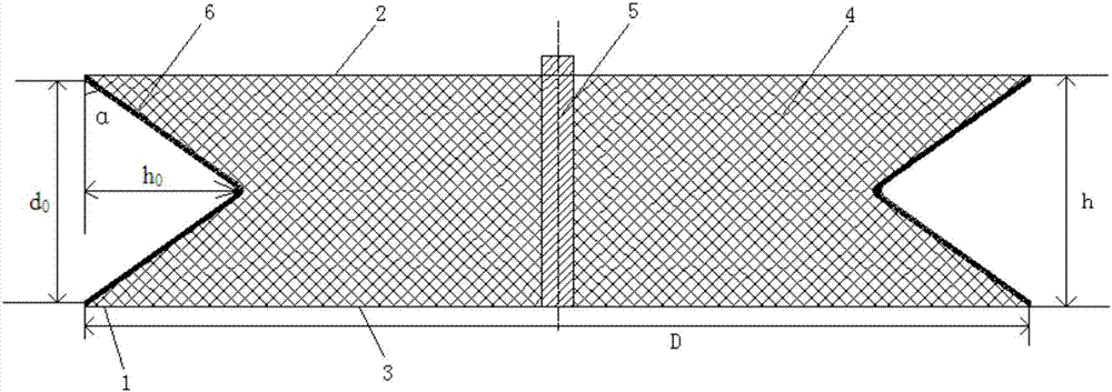
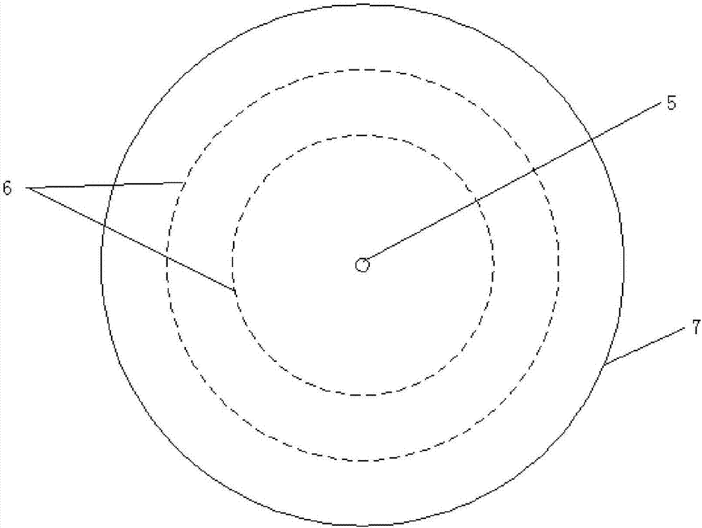
[0039] according to figure 1As shown, the present invention provides a circular plane jet energy-concentrating cutter, comprising: a ring body 1 made of metal, the upper end and the lower end of the ring body 1 are respectively provided with an upper end cover 2 and a lower end cover 3, and the upper end cover 2. A cavity structure is formed between the lower end cover 3 and the ring body 1. Explosives 4 are filled in the cavity, and a detonator tube 5 is inserted on the upper end cover 2 and the lower end cover 3. The ring body 1 The outer wall is provided with a V-shaped groove 6 along the horizontal direction, and the V-shaped opening of the V-shaped groove 6 faces the outside of the annular body. The V-shaped groove 6 is used as an annular energy-gathering cover on the annular body, and the opening of the V-shaped groove 6 The two ends of the end are connected to the u...


PUM


Abstract

The present invention is a circular planar jet energy-concentrating cutter and its use method. The cutter includes a ring body, the upper end and the lower end of the ring body are respectively provided with an upper end cover and a lower end cover, and a cavity is formed between the upper end cover, the lower end cover and the ring body. The cavity is filled with explosives, the upper end cover and the lower end cover are inserted with a detonator, the outer wall of the ring is provided with a V-shaped groove along the horizontal direction, and the V-shaped opening of the V-shaped groove faces the outside of the ring body. In this design, the numerical model and field experiment research and demonstration of the design are carried out in combination with the blasting fracture mechanism of rocks and the mechanical basis of crack expansion, as well as the principle of energy-concentrating blasting. The results show that the annular plane jet energy-concentrating cutter can not only effectively solve the problem of large block rate and root foundation in deep hole blasting in open steps, but also reduce the amount of explosives, fully improve the energy utilization rate of explosives, reduce production costs, and increase productivity. Moreover, the design is simple to operate and easy to use, and can be flexibly stacked and used according to the hardness and strength of different rocks.

Description

Technical field: [0001] The invention relates to the technical field of blasting equipment, in particular to an annular plane jet-flow energy-concentrating cutter and a method for using the same. Background technique: [0002] In the process of open-air step blasting, the generation of foundation and the rate of large blocks are two important indicators to measure the blasting quality, which will directly affect the mining production cost and operating efficiency. In the current rock and mining work, medium and deep hole blasting is still widely used in open-pit step blasting. However, because the broken rock greatly weakens the propagation of the blast stress wave, the rock at the bottom of the step mainly relies on the shearing action generated by the explosion gas expansion to overcome the chassis resistance line. And because the clamping effect of the rock at the bottom of the steps is strong, the explosion energy is often insufficient to form a foundation. [0003] Du...

Claims


Application Information

Patent Timeline
IPC IPC(8): F42D1/00F42D3/04
CPCF42D1/00F42D3/04
Inventor 费鸿禄杨智广蒋安俊谭文华苏强王振达邓政
Owner LIAONING TECHNICAL UNIVERSITY
Learn More