Comb-shaped micro-sensor for measuring strong magnetic field, and preparation method for comb-shaped micro-sensor

A micro-sensor, comb-shaped technology, applied in the field of micro-sensors, can solve the problems of large temperature dependence, lower sensor quality factor, unsuitable for Tokamak high temperature, strong radiation environment, etc.

Active Publication Date: 2017-10-24
HEFEI UNIV OF TECH
View PDF5 Cites 3 Cited by
  • Summary
  • Abstract
  • Description
  • Claims
  • Application Information

AI Technical Summary

Problems solved by technology

However, its temperature dependence is large, and its radiation resistance is poor. After radiation, the quality factor of the sensor will be reduced, and it is not suitable for the high temperature and strong radiation environment inside the tokamak.

Method used


Image

  • Comb-shaped micro-sensor for measuring strong magnetic field, and preparation method for comb-shaped micro-sensor
  • Comb-shaped micro-sensor for measuring strong magnetic field, and preparation method for comb-shaped micro-sensor
  • Comb-shaped micro-sensor for measuring strong magnetic field, and preparation method for comb-shaped micro-sensor

Examples


Embodiment 1

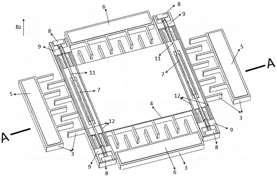
[0054] A comb-tooth microsensor for measuring a strong magnetic field comprises a substrate, a sensor body and a cover connected in sequence.

[0055] The substrate is a single-sided polished wafer 1 with a thickness of 500 um, wherein a cavity with a depth of 1 um is etched by a deep reactive ion etching technique on the polished side, and a lift-off technique is used to grow the entire polished surface provided with a cavity The first silicon oxide layer 2 .

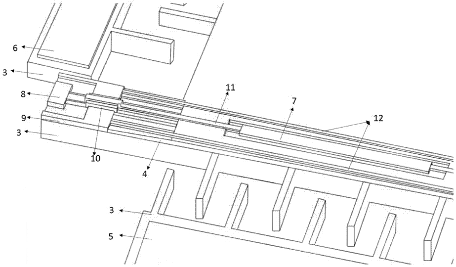
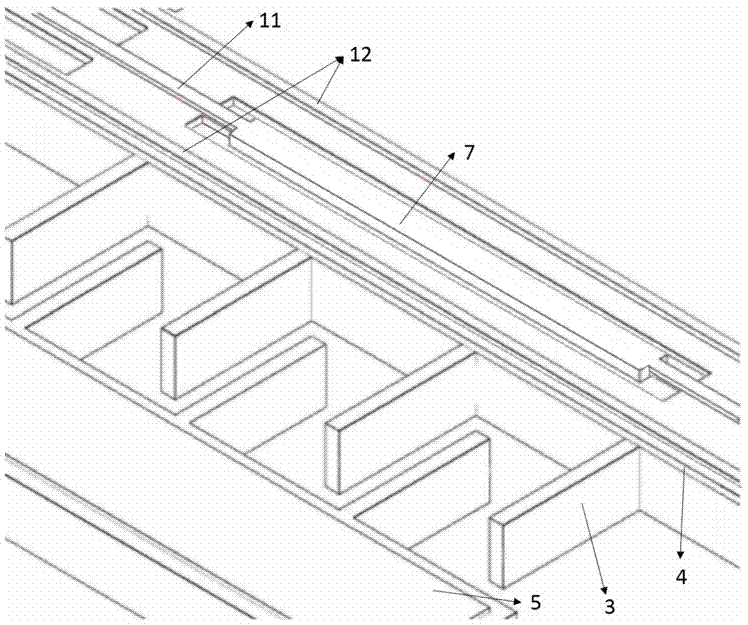
[0056] see figure 1 , the sensor body includes an SOI wafer, the SOI wafer is divided into a main body, a pair of measuring electrode bodies and a pair of driving electrode bodies, a pair of measuring electrode bodies are located on both sides of the main body in the X direction, and a pair of driving electrode bodies are located on the Y side of the main body The two sides of the direction; a pair of measuring electrode bodies and the main body have a tooth-shaped interlaced fit structure, and a pair of driving elect...

Embodiment 2

[0069] The steps of preparing a comb-shaped microsensor for high magnetic field measurement are as follows:

[0070] (1). See Figure 4On the polished side of a 500um thick single-sided polished wafer 1, a 1um deep cavity was etched by deep reactive ion etching technology, and the first oxide was grown by lift-off technique on the entire polished surface provided with the cavity. Silicon layer 2.

[0071] (2). See Figure 5 , at a temperature of 200° C., the 20um thick silicon material layer 3 of the SOI wafer is directly bonded to the first silicon oxide layer 2 of the single-side polished wafer 1 .

[0072] (3). See Image 6 , using deep reactive ion etching to remove the 380um silicon layer 16 on the SOI wafer, and patterning the exposed 1um silicon oxide layer 4 to be etched and removed, and the patterned part exposes a 20um thick silicon material layer 3 , the part of the unpatterned 1um thick silicon oxide layer 4 is in a raised state.

[0073] (4). See Figure 7 A...


PUM


Abstract

The invention relates to a comb-shaped micro-sensor for measuring a strong magnetic field. The micro-sensor comprises a substrate, a sensor body and a cover, wherein the substrate, the sensor body and the cover are connected sequentially. The sensor body comprises three parts: a main body, a pair of measurement electrode bodies and a pair of drive electrode bodies. The pair of measurement electrode bodies are located at two sides of the main body in the X direction, and the pair of drive electrode bodies are located at two sides of the main body in the Y direction, and are respectively symmetric with the main body to form a tooth-shaped staggered cooperative structure. Finally, the substrate, the sensor body and the cover form the comb-shaped micro-sensor with the vacuum interior through bonding. The micro-sensor achieves the measurement of the size of the magnetic field of a Tokamak in a vertical direction z in a strong magnetism environment. A metal coil which lets in an AC signal drives the main body to tend to move in a force-bearing direction under the action of a Lorentz force. The main body is enabled to carry out the mechanical vibration at one frequency under the recombination action of an electrostatic force generated by comb teeth on the drive electrode bodies, thereby causing the capacitance changes, and achieving the calculation of the size of the measured magnetic field.

Description

technical field [0001] The invention belongs to the technical field of microsensors, and in particular relates to a structural design and a preparation process of a comb-shaped microsensor (MEMS) for vertically strong magnetic field measurement. Background technique [0002] With the rapid development of the world economy and the increase of the world's population, human beings' demand for energy is also increasing. The development and utilization of fusion energy is the most promising way to fundamentally solve human energy problems. Among them, the Tokamak device Magnetic confinement fusion research is currently one of the most likely ways to realize the application of fusion energy. The tokamak device is actually a complex high-temperature and strong-radiation electromagnetic system, which uses the magnetic fields generated by various magnet coils to weave into a "magnetic cage "Using the Larmor motion of charged particles in a magnetic field, the high-temperature plasma ...

Claims


Application Information

Patent Timeline
Patent Type & Authority Applications(China)
IPC IPC(8): G01R33/02B81B7/00B81B5/00B81C1/00
CPCB81B5/00B81B7/0038B81C1/00198B81C1/00285G01R33/02
Inventor 许高斌王月媖陈兴马渊明李坤
Owner HEFEI UNIV OF TECH
Why Eureka
Try Eureka