Laser radar ranging system and method based on carrier modulation

A technology of laser radar and ranging system, which is applied in the direction of radio wave measurement system, electromagnetic wave re-radiation, measuring device, etc., can solve the problems of low measurement accuracy and poor anti-interference, achieve high spatial resolution of images, and improve reliability , Improve the effect of measurement accuracy and anti-interference ability

Active Publication Date: 2017-10-27
NINGBO ABAX SENSING ELECTRONICS TECH CO LTD
View PDF5 Cites 17 Cited by
  • Summary
  • Abstract
  • Description
  • Claims
  • Application Information

AI Technical Summary

Problems solved by technology

[0005] Based on the above background, in order to solve the problems of low measurement accuracy and poor anti-interference performance of the existing laser radar ranging system, the present invention provides a laser radar ranging system and ranging system based on carrier modulation with high measurement accuracy and good anti-interference performance. method

Method used


Image

  • Laser radar ranging system and method based on carrier modulation
  • Laser radar ranging system and method based on carrier modulation
  • Laser radar ranging system and method based on carrier modulation

Examples


Embodiment Construction

[0068] The present invention will be described in detail below in conjunction with the accompanying drawings and embodiments.

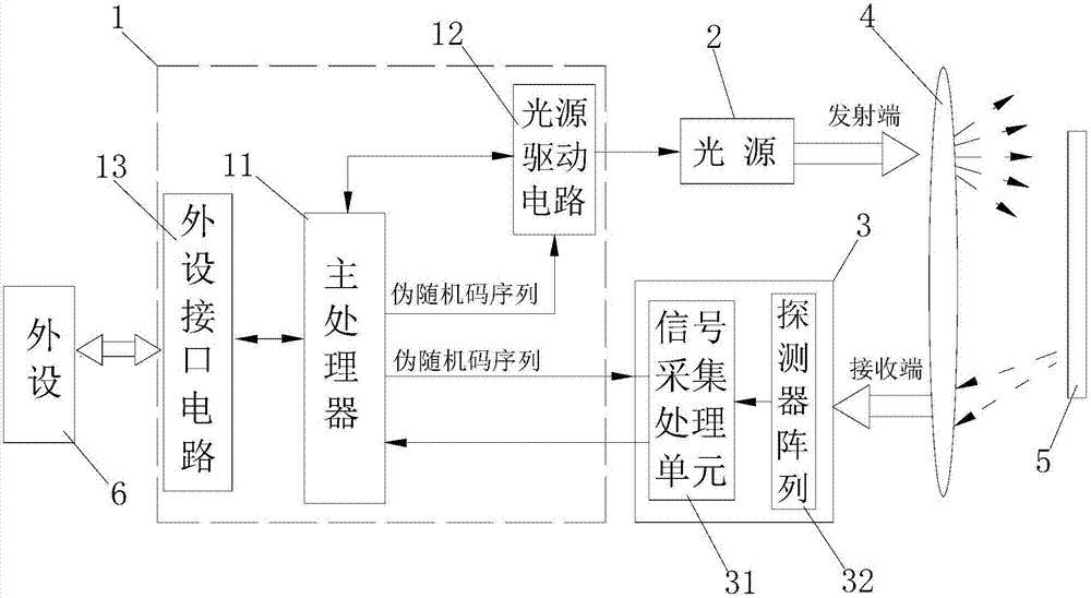
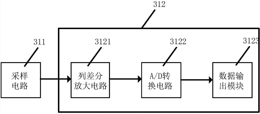
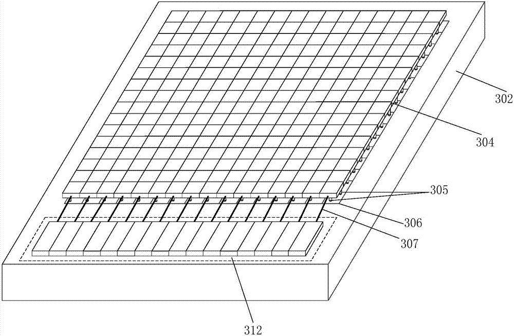
[0069] see Figure 1-8 , the laser radar ranging system provided by the present invention mainly includes a control circuit 1, a light source 2 (surface light source, LED light source or LD light source can be used), an optical system 4, and a detection system composed of a detector array 32 and a signal acquisition and processing unit 31. device 3;

[0070] The control circuit 1 mainly includes a main processor 11, a light source driving circuit 12 and a peripheral interface circuit 13, wherein the output end of the light source driving circuit 12 is connected to the input end of the light source 2, and the I / O ports of the main processor 11 are respectively connected to the detection device 3 , light source drive circuit 12 and peripheral interface circuit 13; main processor 11 can select DSP digital signal processor or select FPGA programmable gat...


PUM


Abstract

In order to solve problems that a conventional laser radar ranging system is low in measurement precision and is poor in anti-interference performance, the invention provides a laser radar ranging system and method based on carrier modulation, wherein the system and method are high in measurement precision, and are good in anti-interference performance. The system comprises a control circuit, a power supply, a detection device, and an optical system. The control circuit comprises a main processor and a light source drive circuit. The main processor is connected with the light source drive circuit and the detection device. The main processor is used for outputting a pseudo-random code sequence. The light source drive circuit employs the pseudo-random code sequence to carry out the low-frequency carrier modulation of an optical signal emitted by a light source. The optical system is used for projecting the optical signal emitted by the light source to a to-be-detected target, gathering the echo signal reflected by the to-be-detected target and projecting the echo signal to the detection device. The detection device carries out the sampling, difference amplifying and A / D conversion of the received echo signal, and outputting a digital signal. The main processor calculates the phase according to the digital signal, and obtains the distance information of the to-be-detected target.

Description

technical field [0001] The invention relates to a laser radar ranging system and a ranging method based on carrier modulation. Background technique [0002] With the development of laser technology, embedded technology and integrated optics, laser ranging is developing in the direction of digitization, automation, low cost and miniaturization. Laser ranging radar has the advantages of high precision, small system size and rapid measurement, and has a wide application prospect. [0003] How to obtain the precise target position in the process of lidar ranging is very important for improving the image resolution, especially for the target vehicle that is constantly moving. Due to the electromagnetic interference inside the vehicle, it is easy to cause the problem of inaccurate measurement. [0004] In addition, most of the traditional vehicle-mounted lidar detectors use a single-point test method, which requires a mechanical scanning device, with slow scanning speed and low s...

Claims


Application Information

Patent Timeline
Patent Type & Authority Applications(China)
IPC IPC(8): G01S17/36G01S17/93G01S7/486
CPCG01S7/4863G01S17/36G01S17/931
Inventor 雷述宇
Owner NINGBO ABAX SENSING ELECTRONICS TECH CO LTD
Why Eureka
Try Eureka