Trench gate RC-IGBT and preparation method thereof

A trench gate and trench technology, which is applied in semiconductor/solid-state device manufacturing, electrical components, circuits, etc., can solve problems such as large reverse recovery peak current, reduced device conduction voltage drop, and uneven current distribution

Inactive Publication Date: 2017-10-27
XIAN UNIV OF TECH
View PDF5 Cites 2 Cited by
  • Summary
  • Abstract
  • Description
  • Claims
  • Application Information

AI Technical Summary

Problems solved by technology

[0007] The purpose of the present invention is to provide a trench gate RC-IGBT, which can greatly reduce the turn-on voltage drop of the device,

Method used


Image

  • Trench gate RC-IGBT and preparation method thereof
  • Trench gate RC-IGBT and preparation method thereof
  • Trench gate RC-IGBT and preparation method thereof

Examples


Embodiment Construction

[0069] The present invention will be described in detail below in conjunction with the accompanying drawings and specific embodiments.

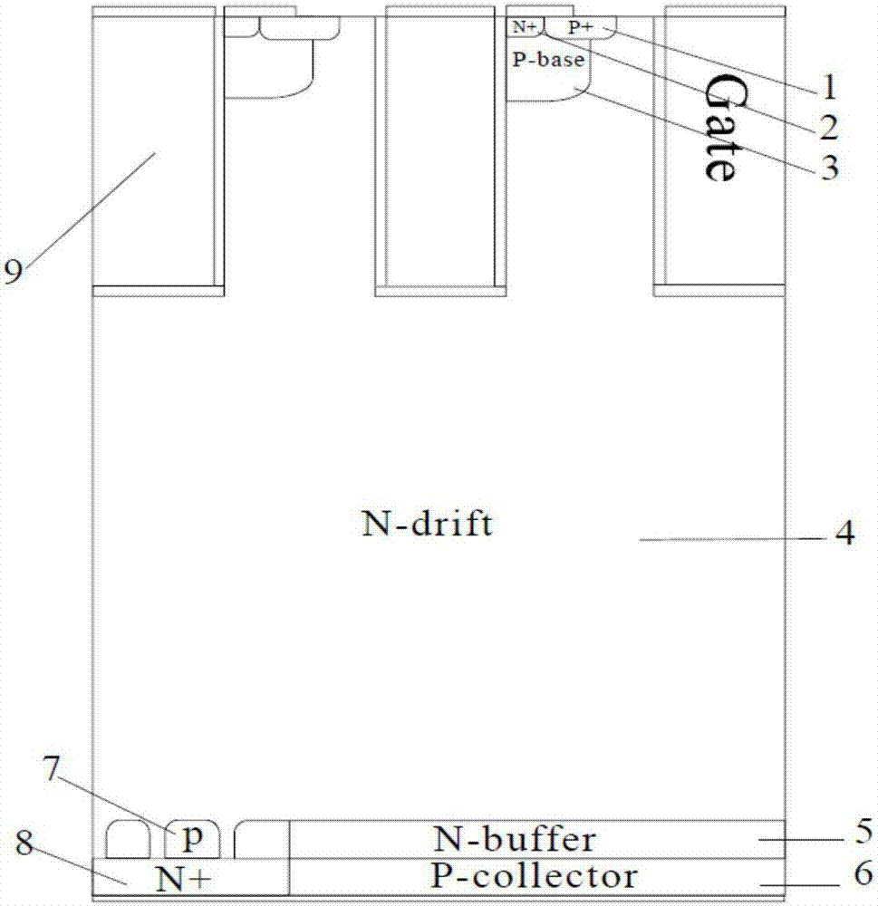
[0070] The present invention provides a trench gate RC-IGBT, such as image 3 shown, including N set sequentially from top to bottom + Emitter 2, P-base area 3, N - Layer 4, the upper surface of P-base area 3 is also provided with P + Emitter 1, P + Emitter 1 and N + Transmitters 2 arranged side by side, N - Several grooves 9 are etched on the upper surface of layer 4, and SiO 2 Gate Oxide, SiO 2 A polysilicon gate is deposited on the gate oxide layer, P + Emitter 1, N + The emitter 2 and the P-base region 3 are located on the same side of the trench 9, and the N + The side walls of the emitter 2 and the P-base region 3 are all in contact with the outer surface of the side wall of the trench 9, N - The back of layer 4 is provided with N buffer layer 5, and the back of N buffer layer 5 is provided with P + Collector 6, P + One side...


PUM

PropertyMeasurementUnit
Groove widthaaaaaaaaaa
Groove depthaaaaaaaaaa
Widthaaaaaaaaaa

Abstract

The invention discloses a trench gate RC-IGBT. The trench gate RC-IGBT comprises N<+> emitting electrodes, P<+> emitting electrodes, P-base regions and an N<-> layer which are sequentially arranged from top to bottom; the P<+> emitting electrodes are arranged on the upper surfaces of the P-base regions, the P<+> emitting electrodes and the N<+> emitting electrodes are arranged side by side, a plurality of grooves are etched on the upper surface of the N<-> layer, SiO2 gate-oxide layers are arranged in the grooves, polysilicon gates are deposited on the SiO2 gate-oxide layers, the P<+> emitting electrodes, the N<+> emitting electrodes and the P-base regions are located on the same sides of the corresponding grooves, and both the side walls of the N<+> emitting electrodes and the side walls of the P-base regions make contact with the outer surfaces of the side walls of the corresponding grooves; and an N buffer layer is arranged on the back face of the N<-> layer, a P<+> collector is arranged on the back face of the N buffer layer, an N<+> collector is arranged on one side of the P<+> collector, and a plurality of P column regions are arranged on the upper surface of the N<+> collector. According to the trench gate RC-IGBT, the problems that in the prior art, current distribution is non-uniform when a traditional RC-IGBT works forwards, and the reverse recovery peak current is too large when the traditional RC-IGBT works reversely are solved, and the forward voltage drop of devices is significantly reduced by means of the RC-IGBT with the novel structure.

Description

technical field [0001] The invention belongs to the technical field of power semiconductor devices, and in particular relates to a trench gate RC-IGBT, and also relates to a preparation method of the trench gate RC-IGBT. Background technique [0002] As electrical energy is widely used in various fields, the power electronics technology developed thereupon is dedicated to the efficient conversion and control of energy, and the power electronic system is determined by power switching semiconductor devices. Therefore, power switching semiconductor devices are the core of the development of contemporary power electronics technology. Power switching semiconductor devices have been developing and advancing along the direction of ideal power switches. The so-called ideal switches specifically refer to low drive power consumption, low on-off state loss, and low conduction loss. IGBT has the advantages of high input impedance of insulated gate field effect transistor, low turn-on v...

Claims


Application Information

Patent Timeline
IPC IPC(8): H01L29/06H01L21/336H01L29/739
CPCH01L29/7393H01L29/0615H01L29/66325
Inventor 马丽李佳豪谢加强康源
Owner XIAN UNIV OF TECH
Why Eureka
Try Eureka