High dynamic range imaging module based on runner dynamic light splitting

A high dynamic range, imaging module technology, applied in image analysis, image communication, image data processing and other directions, can solve the problem of lack of large-scale system-level design and application capabilities, and achieve improved imaging dynamic range, optimal imaging, and quality assurance. Effect

Inactive Publication Date: 2017-10-27
NAT UNIV OF DEFENSE TECH
View PDF7 Cites 7 Cited by
  • Summary
  • Abstract
  • Description
  • Claims
  • Application Information

AI Technical Summary

Problems solved by technology

However, the domestic Changchun Institute of Optics and Mechanics, Zhejiang University, Nankai University, Guizhou University, National University of Defense Technology, Tsinghua University and other units, as well as some optoelectronic research institutes and companies, have made great efforts in camera response curve generation, camera internal and external parameter calibration, image alignment and matching. Accurate, image splicing, optical lens design and manufacture, optical electromechanical structure design, image sensor application control design and other aspects have made good progress, formed the technical strength of sub-modules, and made breakthroughs in the application research of some new devices, For example, the combination of DMD and CCD used by Changchun Institute of Optics and Mechanics to achieve pixel-level exposure control can achieve an imaging dynamic range of 96dB, but there are still many dynamic ranges greater than 120dB (or even 150dB or more) required for shooting range optical measurement imaging. gap
Moreover, the current domestic high dynamic range imaging still lacks large-scale system-level design and application capabilities

Method used


Image

  • High dynamic range imaging module based on runner dynamic light splitting
  • High dynamic range imaging module based on runner dynamic light splitting
  • High dynamic range imaging module based on runner dynamic light splitting

Examples


Embodiment Construction

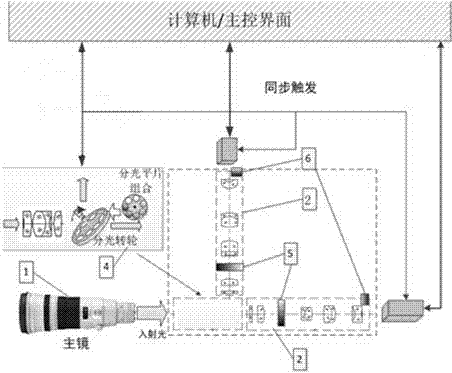
[0026] The structure of the high dynamic range imaging module based on the splitter wheel is as follows figure 1 Shown. The system includes a main mirror 1, an adapter 2, a beam splitter spatial light modulator 4, a camera 7, and a computer main control interface 8. The adapter includes a dynamic adjustable beam splitting mechanism 5, a light intensity dynamic adjustable mechanism 6, and the light collected by the main mirror After the spatial light modulator of the beam splitter, the cameras at different positions are taken into the camera, and the images are imaged on the camera target surface after being collected by the interchangeable adapter at the front of the camera. The dynamic adjustable light splitting mechanism realizes the adjustable light splitting ratio to different cameras according to different imaging tasks, which solves the problem of dynamic adjustment of exposure required for high dynamic range imaging.

[0027] 1 Hardware composition and basic principles

[0...


PUM


Abstract

The invention relates to a high dynamic range imaging module based on runner dynamic light splitting. Through the combination of a primary mirror, a plurality of adapters and a plurality of cameras, a dynamic adjusting technology of parameters such as light splitting ratio, light intensity transmittance, lens stop and camera exposure time and a multi-source image high dynamic synthesis technology are adopted, and clear imaging in a large dynamic range under scene light intensity extreme change conditions is realized, so that the problem of dynamic exposure adjustment required for high dynamic range imaging is solved, and the module is significant for realizing target high-quality imaging in light measurement.

Description

Technical field [0001] The invention relates to the field of sensor high dynamic imaging, in particular to a high dynamic range imaging module based on the dynamic spectroscopy of a runner. Background technique [0002] Because of its non-contact, intuitive, and high-precision characteristics, optical measurement has an irreplaceable role in tasks such as scene recording, abnormal phenomenon analysis, and attitude measurement of new weapons and equipment. However, compared with the high dynamic scene of rocket launch and missile initial flight stage, the existing single set of imaging equipment has a lower dynamic range. Under a certain exposure intensity, it is difficult for the existing equipment to capture all the details in the scene, Part of the details cannot be well exposed and therefore cannot be displayed clearly. Multiple cameras are used to form a camera array, and each camera has a different exposure time. A short exposure time is conducive to capturing the details o...

Claims


Application Information

Patent Timeline
Patent Type & Authority Applications(China)
IPC IPC(8): H04N5/235H04N9/04G06T7/80
CPCG06T7/80H04N23/741H04N23/73H04N23/10
Inventor 于起峰刘肖琳张小虎刘海波
Owner NAT UNIV OF DEFENSE TECH
Why Eureka
Try Eureka