Automatic-zooming laser cleaning head device and cleaning method thereof

A technology of laser cleaning and automatic zooming, applied in cleaning methods and appliances, chemical instruments and methods, optics, etc., can solve problems such as failure to reach, uneven cleaning, and inhalation of metal dust by workers, and meet the requirements of reducing technical proficiency , Avoid poor cleaning effect and reasonable structural design

Pending Publication Date: 2017-11-03
济南高能清扬激光清洗有限公司
View PDF11 Cites 5 Cited by
  • Summary
  • Abstract
  • Description
  • Claims
  • Application Information

AI Technical Summary

Problems solved by technology

The method of mechanical cleaning is to use contact cleaning, which has a mechanical effect on the surface of the object to be cleaned, which is easy to damage the surface of the object to be cleaned, and is also prone to secondary pollution, and the metal dust produced by contact cleaning is easy to be inhaled by workers, affecting workers' health
Laser cleaning has no grinding, non-contact, no thermal effect, and is suitable for cleaning the surface of various materials. It is the most reliable and effective metal cleaning method. At present, although laser cleaning of metal surfaces has been applied, there is a A hand-held laser cleaner, the hand-held laser cleaner in the prior art, in the process of use, requires workers to be able to accurately identify the distance between the hand-held laser cleaner and the cleaning surface, so as to ensure that the laser is on the cleaning surface In many places, the cleaning surface is mostly uneven, which requires workers to accurately adjust the distance between the laser cleaner and the cleaning surface. If the adjustment distance is not accurate, it will lead to uneven cleaning. The cleaning effect is poor, and it cannot meet people's requirements. It requires a lot of technical proficiency of workers, and it is difficult to achieve accurate distance control.

Method used


Image

  • Automatic-zooming laser cleaning head device and cleaning method thereof

Examples


Embodiment Construction

[0017] In order to clearly illustrate the technical features of this solution, the present invention will be described in detail below through specific implementation modes and in conjunction with the accompanying drawings.

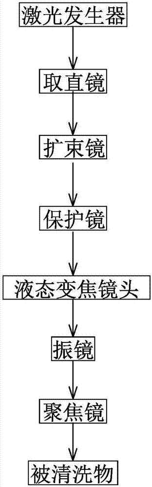
[0018] Such as figure 1 As shown in , an automatic zoom laser cleaning head device includes a laser generator, and the rear side of the laser generator is sequentially provided with a straightening mirror, a protective mirror and a vibrating mirror along the traveling direction of the beam. A beam expander is arranged between the mirrors, a liquid zoom lens is arranged between the protection mirror and the vibrating mirror, and a focusing mirror is arranged on the rear side of the vibrating mirror along the traveling direction of the light beam.

[0019] In the master's degree thesis of the Institute of Precision Engineering of Chung Hsing University published in July 1998 - the research on the value of the variable focus liquid lens module driven by low ...


PUM


Abstract

The invention relates to an automatic-zooming laser cleaning head device and a cleaning method thereof. The automatic-zooming laser cleaning head device comprises a laser generator, a straightening mirror, a protecting mirror and a galvanometer are sequentially arranged on the rear side of the laser generator along the advancing direction of light beams, a beam expanding mirror is arranged between the straightening mirror and the protecting mirror, a liquid-state zooming lens is arranged between the protecting mirror and the galvanometer, and a focusing mirror is arranged on the rear side of the galvanometer along the advancing direction of the light beams. Therefore, the cleaning head device is reasonable and novel in structural design, cleaning of metal with an uneven surface by the laser cleaning head device is ensured effectively, requirements of laser cleaning on technical proficiency of workers are lowered effectively, the workers only need to maintain a distance between the laser cleaning head device and a cleaned face within a certain range, convenience in controlling the laser cleaning head device can be realized, the defect of poor cleaning effect caused by inaccurate distance adjusting is avoided, and uniformity of the laser cleaning head device in cleaning the surface of the metal is ensured effectively.

Description

Technical field: [0001] The invention relates to an automatic zoom laser cleaning head device and a cleaning method thereof. Background technique: [0002] Rust spots, corrosion, oil stains and other pollutant spots often appear on the surface of metal plates. There are many ways to clean metal in the transmission industry. Basically, chemical agents and mechanical methods are used for cleaning. With people's increasing awareness of environmental protection and safety Strengthening, my country's requirements for industrial environmental protection are also getting higher and higher. In the case of meeting environmental protection requirements, there are fewer and fewer types of chemicals that can be used in industrial production cleaning. The method of mechanical cleaning is to use contact cleaning, which has a mechanical effect on the surface of the object to be cleaned, which is easy to damage the surface of the object to be cleaned, and is also prone to secondary pollution...

Claims


Application Information

Patent Timeline
IPC IPC(8): B08B7/00B08B13/00G02B19/00
CPCG02B19/00B08B7/0042B08B13/00
Inventor 李建新李丙琛
Owner 济南高能清扬激光清洗有限公司
Why Eureka
Try Eureka