Eureka AIR delivers breakthrough ideas for toughest innovation challenges, trusted by R&D personnel around the world.

Air cylinder rotor type internal combustion engine

A technology of internal combustion engine and rotor type, which is applied in the direction of internal combustion piston engine, combustion engine, machine/engine, etc. It can solve the problems of reduced service life of the cylinder, impact on sealing performance, emission pollution, etc., and achieve sufficient intake and exhaust, intake and exhaust The effect of improving combustion performance over a long period of time

Inactive Publication Date: 2017-11-03
向元玖
View PDF6 Cites 0 Cited by
  • Summary
  • Abstract
  • Description
  • Claims
  • Application Information

AI Technical Summary

Problems solved by technology

[0003] 1. Due to the vertical component of the crank-connecting rod mechanism acting on the piston after production, not only is the reactive power loss, but also causes periodic changes in the matching gap between the cylinder and the piston, the cylinder wears out of circle, and the increase in the gap between the cylinder and the piston will affect the seal. performance, causing emission pollution and reduced cylinder life
[0004] 2. Since the normal working size of the crank connecting rod is limited, the volume and weight cannot be greatly reduced, the horsepower and weight are relatively low, and the operating cost is high, which cannot meet the requirements of special fields.
like figure 2 However, technical indicators such as small size, light weight, high power, and simple structure are far less ideal than those designed by Wankel.

Method used


Image

  • Air cylinder rotor type internal combustion engine
  • Air cylinder rotor type internal combustion engine
  • Air cylinder rotor type internal combustion engine

Examples


Embodiment Construction

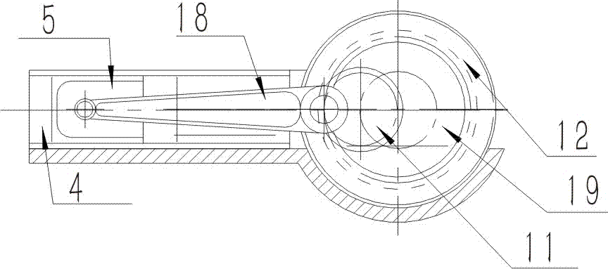
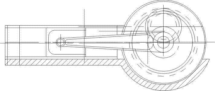
[0032] The following will be combined with Figure 1-Figure 12 The present invention is described in detail, and the technical solutions in the embodiments of the present invention are clearly and completely described. Apparently, the described embodiments are only some of the embodiments of the present invention, not all of them. Based on the embodiments of the present invention, all other embodiments obtained by persons of ordinary skill in the art without making creative efforts belong to the protection scope of the present invention.

[0033] The present invention provides a cylinder rotor type internal combustion engine through improvement, and it is described in detail below in conjunction with its structural principle:

[0034] First of all, we found during the test of the geared engine that as long as the transmission position of the planetary gear is kept fixed, the piston installed on the pitch circle of the planetary gear always takes the initial position as the base ...


PUM


Abstract

The invention discloses an air cylinder rotor type internal combustion engine. The air cylinder rotor type internal combustion engine is characterized by comprising a left bearing cover, an engine body, a rotor, a cylinder body, a piston, a right end cover, a right bearing cover, a left end cover, a rolling bearing A, a rolling bearing B, a planet gear, a sun gear, a rolling bearing C, a rolling bearing D, a gas valve, a sparking plug and a gas valve switch. After improvement, the inner part of a cylindrical cavity of the engine body is separated into two semi-annular cavities through left and right separation walls on a middle plane; an upper cavity is connected with a gas inlet pipe and a lower cavity is connected with an exhaust pipe, so that intake and exhaust are separated and an overlapping angle of the intake and the exhaust is eliminated; and residual waste gas is reduced to the lowest level so that combustion conditions are improved and emission pollution is reduced.

Description

technical field [0001] The invention relates to an engine, in particular to a cylinder rotor type internal combustion engine. Background technique [0002] The traditional internal combustion engine is composed of a cylindrical cylinder, a piston and a crank connecting rod mechanism. It has special advantages such as simple structure, reliable operation, good sealing, and easy manufacture, and has withstood long-term tests in practical applications. Various fields such as production, life, transportation and even national defense have made great contributions to human beings. However, the development of science and technology has also exposed problems that cannot be solved in the process of converting functions and motion forms, such as figure 1 shown. [0003] 1. Due to the vertical component of the crank-connecting rod mechanism acting on the piston after production, not only is the reactive power loss, but also causes periodic changes in the matching gap between the cyli...

Claims


Application Information

Patent Timeline
Patent Type & Authority Applications(China)
IPC IPC(8): F02B53/00F02B53/04F02B53/06F02B55/08F02B55/10
CPCF02B53/00F02B53/04F02B53/06F02B55/08F02B55/10F02B2053/005Y02T10/12
Inventor 向元玖
Owner 向元玖
Why Eureka
Eureka Blog
Learn More