Vane type diffuser assembly for gas compressor and assembly method for vane type diffuser assembly

A diffuser and blade-type technology, which is applied in the field of compressor blade-type diffuser components and its assembly, can solve the problem of affecting the smoothness of the air inlet flow path of the compressor, affecting the air intake efficiency of the compressor, and low welding efficiency. problems, to achieve the effect of improving market competitiveness, improving the effect of deceleration and boosting, and improving the welding rate

Pending Publication Date: 2017-11-03
CHINA HANGFA CHANGZHOU LANXIANG MACHINERY CO LTD
View PDF6 Cites 1 Cited by
  • Summary
  • Abstract
  • Description
  • Claims
  • Application Information

AI Technical Summary

Problems solved by technology

[0003] When installing the existing compressor vane diffuser assembly, it is necessary to braze the vane diffuser and the front and rear cover plates to form an assembly, such as figure 1 As shown, when assembling, it is necessary to braze the place where the blade is in contact with the front cover 2 and the rear cover 3 along the periphery of the blade 1 (that is, the welding point 4). Since the welding seam is very narrow and long, and the welding is performed in a relatively narrow space, The difficulty is high, and the welding efficiency is low, which affects the efficiency. At the same time, it is very easy to desolder during use, which poses a safety hazard; and the welding seam is in the flow channel between the front cover and the rear cover, which affects the air flow of the compressor air intake. Smoothness, which affects the intake efficiency of the compressor

Method used


Image

  • Vane type diffuser assembly for gas compressor and assembly method for vane type diffuser assembly
  • Vane type diffuser assembly for gas compressor and assembly method for vane type diffuser assembly

Examples


Embodiment 1

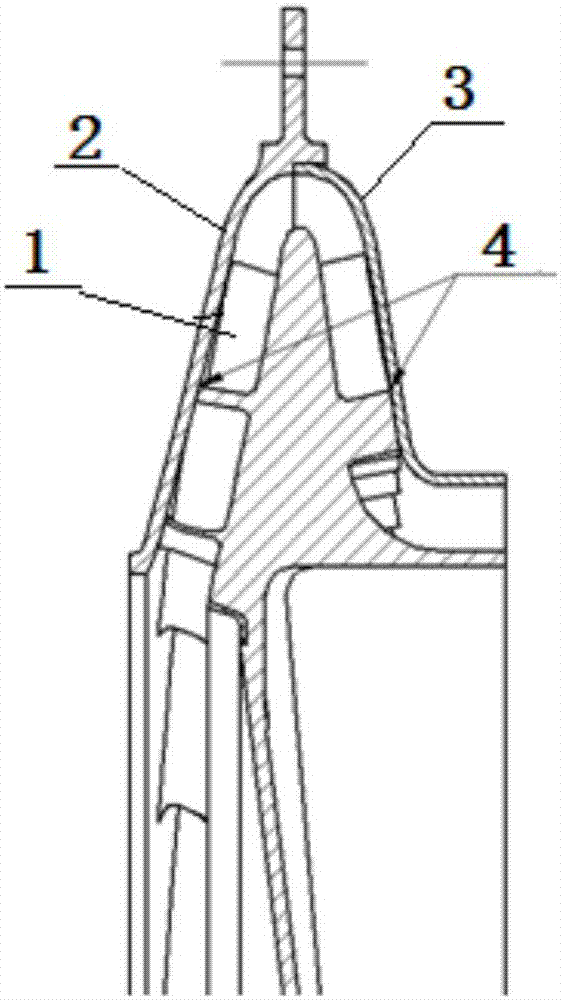
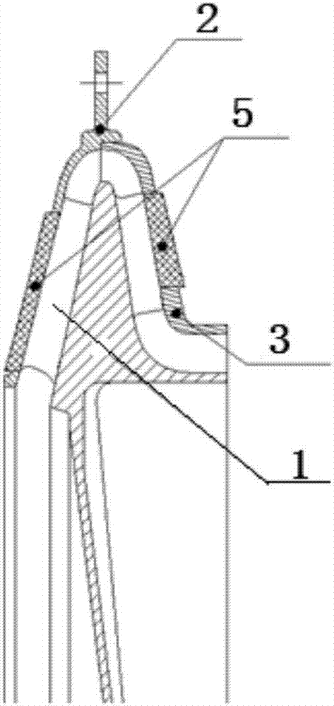
[0021] Example 1 as figure 2 As shown, the vane diffuser assembly for the compressor of the present embodiment includes a front cover 2, a rear cover 3 and a vane diffuser, and the blades of the vane diffuser and the front cover 2 and the rear cover 3 are welded 1. A boss 5 is grown at the blade tip through 3D printing additive manufacturing. The material used for 3D printing additive manufacturing at the blade tip is the same 0Cr17Ni4Cu4Nb powder as the base material. The particle size specification of the powder is -90 mesh. The strength of the boss is similar to the strength of the base material. The welded part of the front cover 2, the rear cover 3 and the vane diffuser adopts an electric machining method to process the airfoil groove suitable for the passage of the boss 5, so that the boss 5 protrudes through the airfoil groove and is arranged on the On the outer sides of the front cover 2 and the rear cover 3, the boss 5 is welded and fixed to the outer sides of the f...


PUM

PropertyMeasurementUnit
particle size (mesh)aaaaaaaaaa

Abstract

The invention relates to a vane type diffuser assembly for a gas compressor and an assembly method for the vane type diffuser assembly. The vane type diffuser assembly for the gas compressor comprises a front cover, a rear cover and a vane type diffuser. A boss is added in the position, welded to the front cover and the rear cover, of the valve tip of the vane type diffuser in a 3D printing additive manufacturing mode, and the bonding strength of the boss and a valve base body is equivalent to that of the boss and a base material. The welding position of the front cover, the rear cover and the vane type diffuser is provided with a vane-shaped groove suitable for being penetrated through by the boss, so that the boss penetrates through the vane-shaped groove and protrudes on the outer sides of the front cover and the rear cover. The boss is fixedly welded to the outer sides of the front cover and the rear cover. The welding difficulty is lowered. A weld joint is located in the opposite outer sides of the front cover and the rear cover, the influence on gas inlet channels of the front cover and the rear cover is avoided, and the obtained vane type diffuser assembly for the gas compressor is firm, reliable and easy to weld.

Description

technical field [0001] The invention relates to the technical field of aero-engines, in particular to a bladed diffuser assembly for a compressor and an assembly method thereof. Background technique [0002] Compared with reciprocating compressors, impeller compressors such as centrifugal compressors have the advantages of high efficiency, small size, light weight and stable operation. The vane diffuser is an important part of the centrifugal compressor. Its function is to deflect the airflow direction at the outlet of the centrifugal impeller at a desired angle, improve the diffusion capacity, and expand the stable operating range of the compressor. [0003] When installing the existing compressor vane diffuser assembly, it is necessary to braze the vane diffuser and the front and rear cover plates to form an assembly, such as figure 1 As shown, when assembling, it is necessary to braze the place where the blade is in contact with the front cover 2 and the rear cover 3 alo...

Claims


Application Information

Patent Timeline
Patent Type & Authority Applications(China)
IPC IPC(8): F04D29/44F04D29/02B23P15/00
CPCF04D29/023F04D29/444B23P15/00
Inventor 陈少俊王豫宁卢文海李伟超沈稼耕
Owner CHINA HANGFA CHANGZHOU LANXIANG MACHINERY CO LTD
Why Eureka
Try Eureka