
Method for determining diffusion coefficient of carbon dioxide in porous medium

A technique for carbon dioxide, diffusion coefficient, applied in diffusion analysis, analysis of suspensions and porous materials, measurement devices, etc., can solve problems such as not mentioned

Active Publication Date: 2017-11-03
CHINA PETROLEUM & CHEM CORP +1
View PDF5 Cites 12 Cited by
  • Summary
  • Abstract
  • Description
  • Claims
  • Application Information

AI Technical Summary

Problems solved by technology

The gas-liquid diffusion process is detected by MRI technology, which realizes the microscopic visualization and quantitative analysis of the gas-liquid system diffusion process in porous media, and quantitative analysis of important parameters such as porosity, permeability and saturation of porous media; the device of this patent Through MRI technology, the proton density image, longitudinal and transverse relaxation time, apparent diffusion coefficient and diffusion tensor distribution image of the fluid in the porous medium can be measured in real time, intuitively and without damage, so as to realize the visualization of the entire diffusion process, but This invention does not mention the use of nuclear magnetic resonance technology to obtain the diffusion coefficient of gas and liquid, but can determine the diffusion coefficient of gas in a rock core saturated with liquid through an improved double-chamber pressure decay method

Method used


Image

  • Method for determining diffusion coefficient of carbon dioxide in porous medium
  • Method for determining diffusion coefficient of carbon dioxide in porous medium

Examples


Embodiment 1

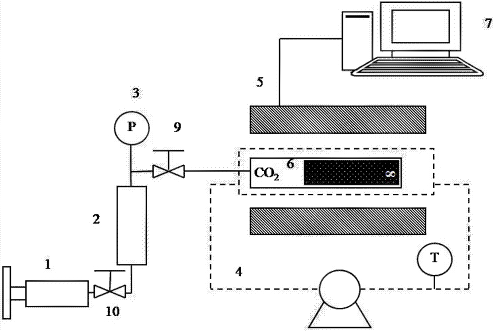
[0045] The permeability of the cylindrical core used is 0.218mD, the length L of the core is 5.366cm, and the diameter is 2.487cm; the diffusion pressure is 12MPa, and the diffusion temperature is 45°C. The specific experimental determination steps are as follows:

[0046] 1) One end face and all sides of the rock core 8 saturated with crude oil are sealed with epoxy resin;

[0047] 2) Put the sealed rock core 8 into the diffuser cylinder 6, and the sealed end surface of the rock core 8 is in contact with the bottom of the diffuser cylinder 6;

[0048] 3) Heat the diffusion cylinder 6 to 45°C through the temperature cycle control system 4, and keep the diffusion cylinder 6 at a constant temperature;

[0049] 4) Open the valve 10, utilize the injection pump 1 to pressurize the carbon dioxide container 2 to 12MPa, and keep the injection pump 1 in a constant pressure state; the pressure sensor 3 shows the pressure in the carbon dioxide container 2;

[0050] 5) Open the valve 9,...


PUM

PropertyMeasurementUnit
diameteraaaaaaaaaa

Abstract

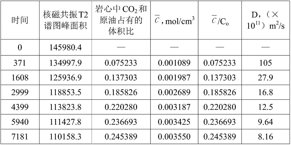
The present invention provides a method for determining the diffusion coefficient of carbon dioxide in a porous medium. The method comprises: sealing all surfaces of rock core saturated with crude oil; placing the sealed rock core in a diffusion cylinder; heating the diffusion cylinder to achieve a desired temperature, and maintain the constant temperature; opening a valve, pressurizing a carbon dioxide container to achieve a desired pressure, and maintaining the constant pressure; opening a valve, and injecting CO2 into the diffuser cylinder under the constant pressure; measuring the rock core in the diffusion cylinder through a nuclear magnetic resonance system to obtain a T2 spectrum; calculating the volume proportions of the CO2 and the crude oil in the rock core by using the peak area in the T2 spectrum; and calculating the molar concentration of the CO2 in the rock core, calculating the molar concentration C of the CO2 in the rock core under different diffusion time conditions to obtain an average concentration C<->, and substituting the average concentration C<-> into a formula defined in the specification to obtain the diffusion coefficient D. According to the present invention, with the method, the visualized calculation and the quantitative analysis of the diffusion coefficient by using the T2 magnetic resonance spectrum is achieved.

Description

technical field [0001] The invention relates to the field of oil and gas field development, more specifically, relates to a method for measuring CO by using nuclear magnetic resonance T2 spectrum 2 A method for diffusivity in dense porous media saturated with crude oil. Background technique [0002] The methods for measuring the diffusion coefficient of gas in porous media in the current literature are generally divided into two categories: direct method and indirect method. Whether it is direct or indirect measurement, it can only describe the concentration or diffusion of the gas in the diffusion medium, but cannot directly measure the diffusion coefficient of the gas, that is, the diffusion coefficient of the gas in the porous medium must be determined by the laboratory combined with the model Calculations can be determined. [0003] (1) Direct method: sample the fluid at different times and different diffusion distances, then analyze these samples to obtain the gas con...

Claims


Application Information

Patent Timeline
Patent Type & Authority Applications(China)
IPC IPC(8): G01N13/00G01N15/08G01N24/08
CPCG01N13/00G01N15/08G01N24/082G01N2013/003
Inventor 王海涛伦增珉吕成远潘伟义郎东江骆铭赵淑霞王友启赵春鹏刘玄龚凯
Owner CHINA PETROLEUM & CHEM CORP
Learn More