
Radar netting target state and system error joint estimation algorithm

A technology of system error and target state, applied in radio wave measurement system, radio wave reflection/re-radiation, utilization of re-radiation, etc., can solve problems such as reduced filtering accuracy, measurement error, and reduced filtering accuracy

Active Publication Date: 2017-11-03
LEIHUA ELECTRONICS TECH RES INST AVIATION IND OF CHINA
View PDF3 Cites 15 Cited by
  • Summary
  • Abstract
  • Description
  • Claims
  • Application Information

AI Technical Summary

Problems solved by technology

[0004] ① Although the spherical (polar) projection method uses high-order approximation to improve accuracy, since the earth is an ellipsoid rather than a sphere, it will introduce errors to the measurement during projection;
[0005] ②The spherical (polar) projection method will distort the data
Spherical (polar) conformal projection only guarantees that the azimuth angle will not be deformed, but it cannot guarantee that the slope distance will not be deformed, which will cause the system error to no longer be constant and related to measurement;
[0006] ③In the two-dimensional public coordinate system, only the systematic error of azimuth and radial distance can be estimated, but the systematic error of pitch angle cannot be estimated
However, EKF needs to calculate the Jacobian matrix. In the case of high-precision measurement, high-dimensional system, and complex and strong nonlinearity, it often cannot approximate the posterior probability density function of the system state very well, resulting in a greatly reduced filtering accuracy, and even causing filtering diverge
Although UKF avoids the shortcomings of EKF and improves the estimation accuracy to a certain extent, when UKF is applied to high-dimensional nonlinear systems, the weights of its deterministic sampling points are prone to negative values, which leads to the introduction of truncation errors in its moment integrals, which cannot Ensure numerical stability and semi-positive definiteness of the state covariance matrix, resulting in a decrease in filtering accuracy

Method used


Image

  • Radar netting target state and system error joint estimation algorithm
  • Radar netting target state and system error joint estimation algorithm
  • Radar netting target state and system error joint estimation algorithm

Examples


Embodiment Construction

[0079] In order to make the objectives, technical solutions and advantages of the present invention clearer, the technical solutions in the embodiments of the present invention will be described in more detail below in conjunction with the drawings in the embodiments of the present invention. In the drawings, the same or similar reference numerals denote the same or similar elements or elements having the same or similar functions throughout. The described embodiments are some, but not all, embodiments of the invention. The embodiments described below by referring to the figures are exemplary and are intended to explain the present invention and should not be construed as limiting the present invention. Based on the embodiments of the present invention, all other embodiments obtained by persons of ordinary skill in the art without creative efforts fall within the protection scope of the present invention.

[0080] The radar network target state and system error joint estimati...


PUM


Abstract

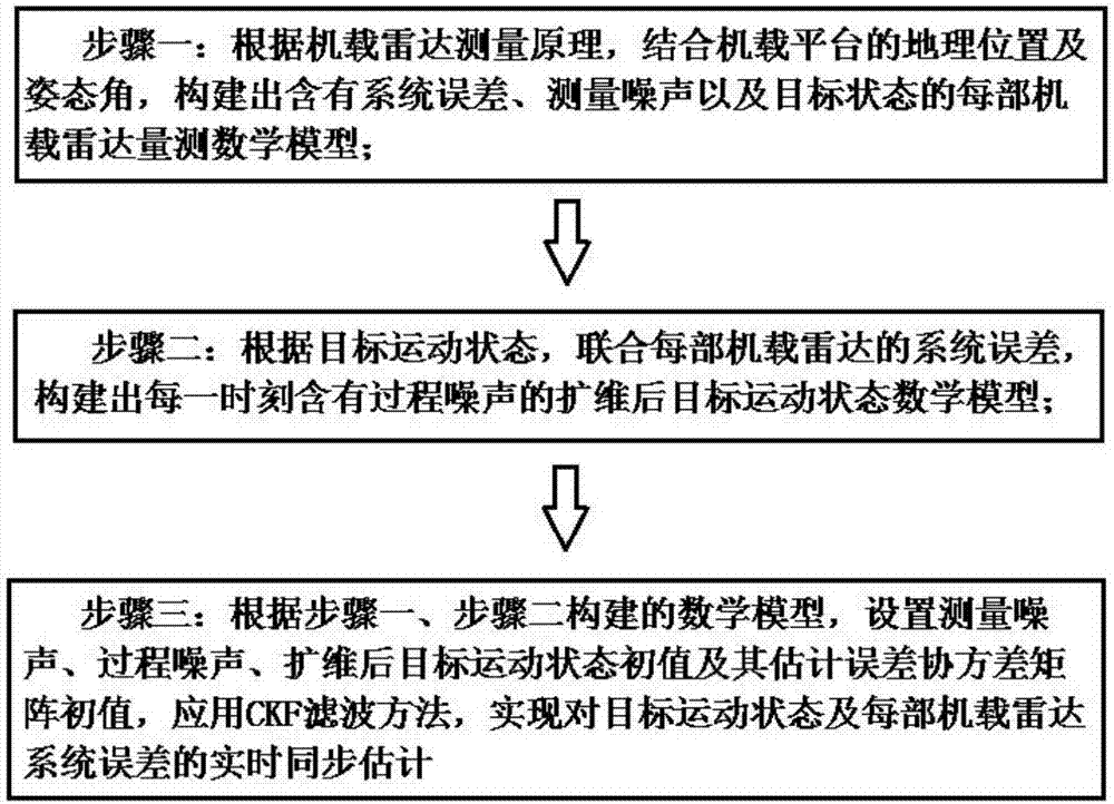
The invention provides a radar netting target state and system error joint estimation algorithm. The algorithm comprises the following steps: according to an airborne radar measurement principle, in combination of a geographical position and an attitude angle of an airborne platform, a measurement mathematical model for each airborne radar with system errors, measurement noise and the target state included is constructed; according to the target motion state, in joint of the system errors of each airborne radar, a target motion state mathematical model after dimension expansion with process noise included at each moment is constructed; and according to the constructed mathematical models in the former two steps, initial values of the measurement noise, the process noise, the target motion state after dimension expansion and an estimation error covariance matrix are set, a CKF filter method is applied, and real-time and synchronous estimation on the target motion state and the system errors of each airborne radar is realized. Problems that data deformation exists in the traditional coordinate projection-based two-dimensional planar system error registration algorithm, errors of a pitch system can not be estimated and the traditional method is not suitable for long-distance system error registration can be solved.

Description

technical field [0001] The invention relates to the field of radar networking information fusion target tracking, in particular to the field of multi-platform cooperative tracking of airborne radar under the conditions of high measurement accuracy, high system dimension, and complex strong nonlinearity, and specifically relates to a radar networking target state Joint estimation algorithm with systematic error. Background technique [0002] The huge benefits that radar networking information fusion can bring have been recognized by countries all over the world. Although radar networking information fusion technology is still developing rapidly, due to the existence of radar detection target errors in the actual system, the guarantee of system real-time fusion effect has become a very difficult problem in the field of radar networking information fusion technology for a long time. Practical application shows that in multi-radar network tracking system, the existence of radar...

Claims


Application Information

Patent Timeline
IPC IPC(8): G01S7/40G01S13/87G01S13/72
CPCG01S7/40G01S13/723G01S13/87
Inventor 程然张敏王婷婷
Owner LEIHUA ELECTRONICS TECH RES INST AVIATION IND OF CHINA
Learn More