
Calibration method of array antenna receiving system of navigation satellite

A navigation satellite and array antenna technology, applied in the field of navigation satellite signal processing, can solve problems such as affecting the code phase and carrier phase of satellite navigation signals, uncontrollable phase deviation, optimal signal-to-noise ratio, and destruction of navigation satellite signal phase information, etc. Flexible channel calibration mechanism, enhancing the useful signal, suppressing the effect of interference

Active Publication Date: 2017-11-03
10TH RES INST OF CETC
View PDF11 Cites 42 Cited by
  • Summary
  • Abstract
  • Description
  • Claims
  • Application Information

AI Technical Summary

Problems solved by technology

[0005] When the traditional array processing algorithm is applied to the satellite navigation system, it will inevitably affect the code phase and carrier phase of the satellite navigation signal, and the phase information of the navigation satellite signal is closely related to the position relationship, which will directly affect the positioning and timing function of the receiving system
Since the non-omnidirectional characteristics of the antenna and the inconsistency of the channel will lead to the destruction of the phase information of the navigation satellite signal, the inaccurate antenna array steering vector will lead to the inability to control the phase deviation brought by the array processing to the specific satellite signal and obtain the optimal SNR

Method used


Image

  • Calibration method of array antenna receiving system of navigation satellite
  • Calibration method of array antenna receiving system of navigation satellite
  • Calibration method of array antenna receiving system of navigation satellite

Examples


Embodiment Construction

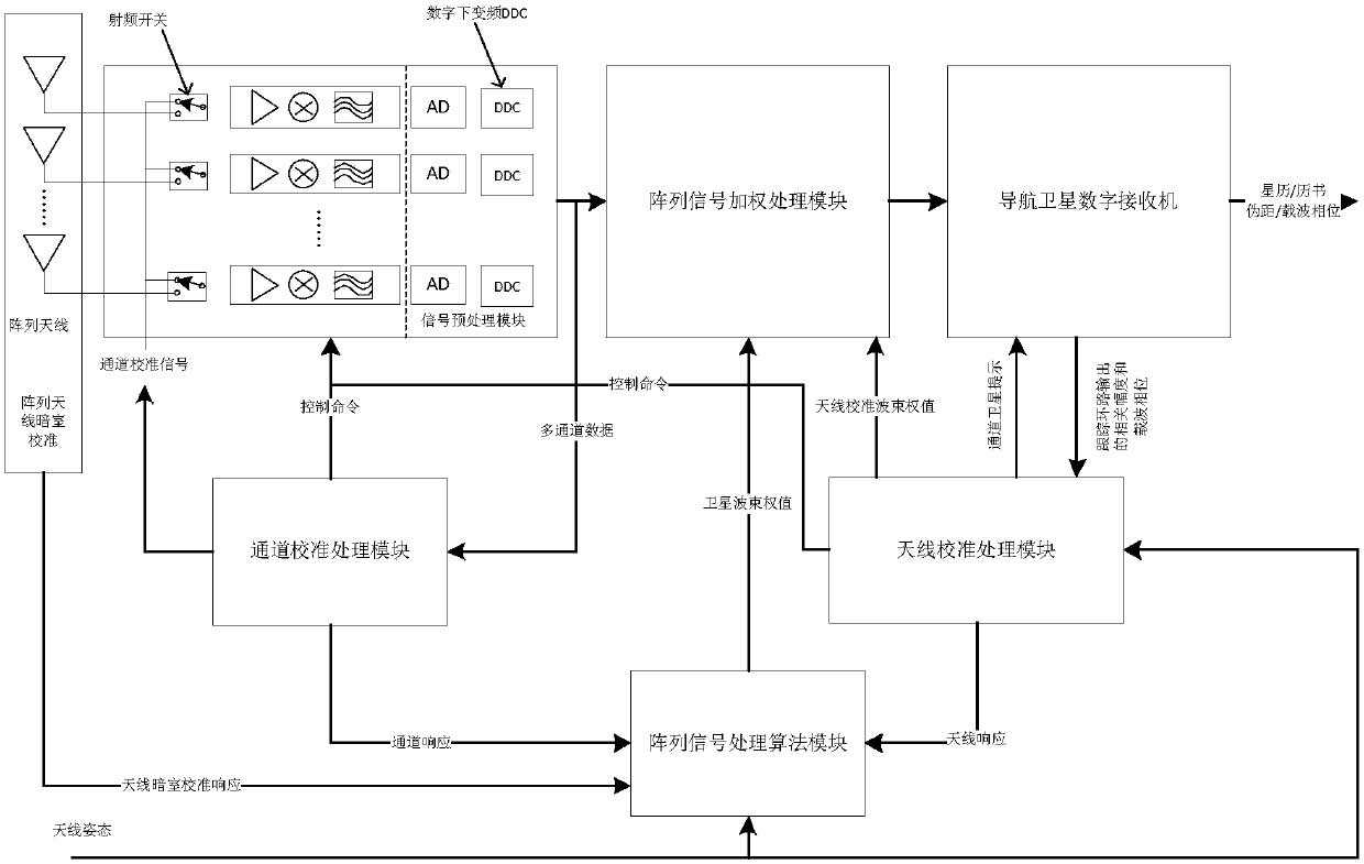
[0020] refer to figure 1 . The entire navigation array antenna receiving system can be divided into two parts: channel calibration and antenna calibration, which are switched between two modes. The two modes are switched by control commands. The array antenna forms an antenna calibration channel through a radio frequency switch and a multi-channel analog-to-digital converter AD. The antenna calibration channel is connected to the navigation satellite digital receiver through the array signal weighting processing module DBF, and is connected to the array signal weighting processing module DBF through the channel calibration processing module. The array signal processing algorithm module, the array signal processing algorithm module is connected to the array signal weighting processing module DBF, and is connected between the channel calibration processing module and the antenna calibration processing module, and the antenna calibration processing module transmits control comman...


PUM


Abstract

The invention provides a calibration method of an array antenna receiving system of a navigation satellite. The objective of the invention is to provide the calibration method which is capable of restraining interference and improving estimation accuracy of guidance vectors of the antenna array. The calibration method comprises steps of during channel calibration, sending multi-channel data output by multiple paths of analog-digital converters into a channel calibration processing module for channel calibration signal processing, measuring inconsistency between channels, successively selecting at least two channels from the channels, keeping the other channels to be normally operated, updating channel consistency response along with the time change, calculating to obtain channel responses used by an array processing algorithm module, and finishing the channel calibration; and during antenna calibration, by taking satellite signals as measurement signals, multiple paths of antenna calibration signals are synthesized through an array signal weighting processing module DBF and then sent to a navigation satellite digital receiver, outputting the antenna calibration signals to an antenna calibration processing module, calculating antenna responses of the array in the incidence direction of the satellite signals and finishing the antenna calibration.

Description

technical field [0001] The invention relates to a calibration method widely used in array antenna receiving systems in fields such as radar, sonar, wireless communication and the like. Specifically, it is about the field of navigation satellite signal processing, which is applied to the system using array antennas to receive and process navigation satellite signals, and supports a calibration method that improves the signal-to-interference-noise ratio and stabilizes the phase center array processing capability. Background technique [0002] The satellite navigation system is a system based on radio ranging. The antenna is a key part to realize the reception and transmission of radio signals. The directivity, polarization characteristics, working bandwidth characteristics and phase stability of the antenna directly determine the service quality of the satellite navigation system. . The problem of weak signal and susceptibility to interference of satellite navigation system i...

Claims


Application Information

Patent Timeline
IPC IPC(8): G01S19/23
CPCG01S19/235
Inventor 李阳王海砚康荣雷甘明
Owner 10TH RES INST OF CETC
Learn More