Automatic assembling device of rotor and end cover of permanent magnet synchronous motor

A permanent magnet synchronous motor and rotor technology, used in electromechanical devices, electric components, manufacturing of motor generators, etc., can solve problems such as motor vibration and abnormal noise, end cover deformation, and uneven matching.

Active Publication Date: 2017-11-03
SHANGHAI EDRIVE +2
View PDF8 Cites 2 Cited by
  • Summary
  • Abstract
  • Description
  • Claims
  • Application Information

AI Technical Summary

Problems solved by technology

[0003] The installation of the permanent magnet synchronous motor rotor and end cover is a very important process in the motor assembly process. The existing assembly process is to use the cylinder pressure rod to press the rotor into the casing assembly, and then the operator uses a hammer to hit the end cover , to complete the cooperation between the end cover and the bearing and the casing assembly. This operation method causes several problems: First, because the rotor is plugged with magnetic steel with magnetic force, during the process of pressing the rotor, it is attracted by the inner wall of the stator du

Method used


Image

  • Automatic assembling device of rotor and end cover of permanent magnet synchronous motor
  • Automatic assembling device of rotor and end cover of permanent magnet synchronous motor
  • Automatic assembling device of rotor and end cover of permanent magnet synchronous motor

Examples


Embodiment Construction

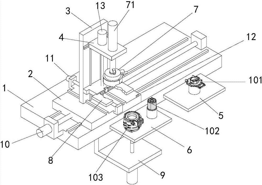
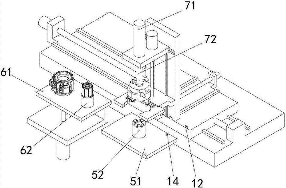
[0043] See figure 1 , See for cooperation Figure 2 to Figure 11 . The automatic assembly device of the permanent magnet synchronous motor rotor and end cover of the present invention includes an end cover 101, a rotor assembly 102 and a casing assembly 103. The automatic assembly device of a permanent magnet synchronous motor rotor and end cover includes Fixed platform 1, horizontal movement platform 2, radial movement platform 3, support platform 4, end cover transfer platform 5, rotor and casing transfer platform 6, end cover grabbing assembly 7, rotor grabbing assembly 8 and ejector rod assembly 9 .

[0044] A horizontal movement motor 10 is installed on the fixed platform 1.

[0045] The horizontal movement platform 2 is erected on the fixed platform 1 and can move horizontally along the fixed platform under the drive of the horizontal movement motor 10. A radial movement motor 11 and a radial displacement sensor 12 are installed on the horizontal movement platform.

[0046] T...


PUM


Abstract

The invention provides an automatic assembling device of a rotor and an end cover of a permanent magnet synchronous motor. The automatic assembling device comprises a fixed platform, a horizontal moving platform, a radical moving platform, a supporting platform, an end cover transferring platform, a rotor and case transferring platform, an end cover gripping assembly, a rotor gripping assembly and an ejector rod assembly, wherein the end cover gripping assembly comprises a pushing cylinder, a pushing rod assembly, an end cover gripper fixing platform and an end cover gripper; and the rotor gripping assembly comprises a rotor gripper fixing platform, a rotor gripper and a bidirectional cylinder. The working process of the device provided by the invention comprises the steps of firstly gripping the end cover of the motor, then gripping the rotor of the motor, and finally completing the assembling of the rotor and the end cover of the motor, so that the problem of rotor displacement generated by magnetic force attraction with the inner wall of a stator in the process that the rotor of the permanent magnet synchronous motor is pressed is solved, and the problems that the end cover is deformed and the cooperation is non-uniform caused by knocking when the end cover of the permanent magnet synchronous motor is mounted are solved.

Description

Technical field [0001] The invention relates to tooling, in particular to an automatic assembly device for a rotor and an end cover of a permanent magnet synchronous motor. Background technique [0002] Because permanent magnet synchronous motors have the advantages of simple structure, small size, fast response, wide speed range, high power factor, etc., they have been increasingly used in the new energy automobile industry, and have been widely used with the rise of the new energy automobile industry. The application also puts forward requirements for the stability of permanent magnet motor operation and noise reduction. [0003] The installation of the rotor and end cover of the permanent magnet synchronous motor is a very important process in the motor assembly process. The existing assembly process uses a cylinder pressure rod to press the rotor into the housing assembly, and then the operator uses a hammer to hit the end cover , To complete the matching of the end cover with...

Claims


Application Information

Patent Timeline
IPC IPC(8): H02K15/00H02K15/16
CPCH02K15/00H02K15/16Y02T10/64
Inventor 赵凯应红亮贡俊
Owner SHANGHAI EDRIVE
Why Eureka
Try Eureka