A device and method for laser drilling of annular heat shield

A laser drilling and heat shield technology, applied in auxiliary devices, laser welding equipment, auxiliary welding equipment and other directions, can solve the problems of difficult parts clamping, affecting the processing progress of parts, and difficult clamping, etc., to achieve easy clamping and The effect of cutting, improving work efficiency and simple structure

Active Publication Date: 2019-11-08
CHINA HANGFA GUIZHOU LIYANG AVIATION POWER CO LTD
View PDF8 Cites 0 Cited by
  • Summary
  • Abstract
  • Description
  • Claims
  • Application Information

AI Technical Summary

Problems solved by technology

In the processing process, due to the large number of small holes in the parts, the difficulty in clamping the parts, and the need to reposition and align when replacing parts, the processing cycle is long, and the delivery task of a single part is difficult to complete on time, which is the time bottleneck of the overall delivery.
[0003] The existing tooling structure is complicated, the manufacturing cycle is long, and the available tooling cannot be provided on time, and there are difficulties in clamping and inaccurate positioning during the use of the tooling: the diameter of such characteristic sheet metal parts is greater than 900mm, and the height is greater than 140mm, resulting in The shape and size of the tooling are large, and the tooling is made of carbon steel as the raw material, which makes the tooling heavy; there is no mechanism for actively aligning with the equipment workbench during the clamping process, which requires manual adjustment of the tooling during the clamping process, which consumes a lot of time; This kind of characteristic sheet metal parts are all wave-shaped annular cylindrical parts, but the diameters of the parts are different, which makes the part tooling unable to be used universally, the tooling utilization rate is low, and the manufacturing cycle is long, which seriously affects the part processing progress

Method used


Image

  • A device and method for laser drilling of annular heat shield
  • A device and method for laser drilling of annular heat shield
  • A device and method for laser drilling of annular heat shield

Examples


Embodiment Construction

[0028] The technical solution of the present invention is further described below in conjunction with the accompanying drawings, but the scope of protection is not limited to the description.

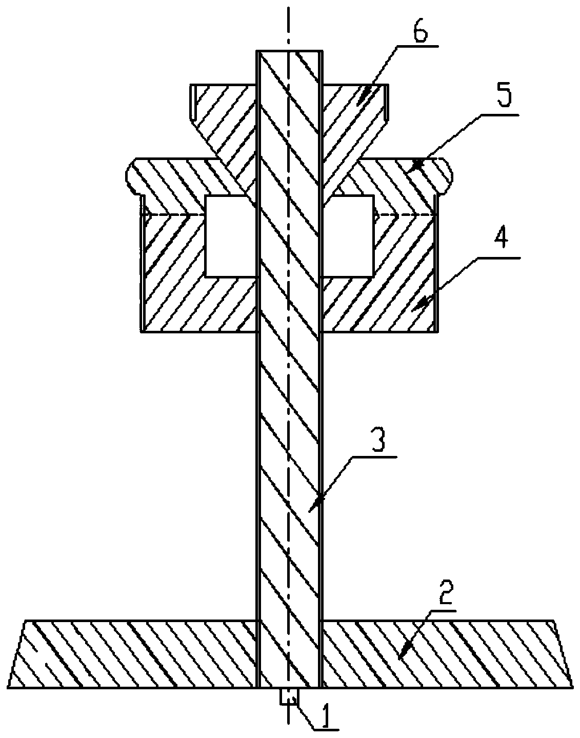
[0029] Such as Figure 3-6 As shown, the present invention includes a screw rod 3 with automatic alignment and centering effect on the laser drilling machine operating platform. The material used for the screw rod 3 is stainless steel, and its outer surface is threaded throughout. The height of the expansion disc 5 is suitable for the processing of parts with different heights; the bottom of the screw 3 is drilled with a threaded hole matching the positioning pin 1, and the function is to make the axis center of the threaded rod 3 coincide with the center of the console by connecting the positioning pin 1 to realize automatic Correction function;

[0030] It has a stabilizing plate 2 for stabilizing the screw 3 on the laser drilling machine operating platform. The material of the stabi...


PUM


Abstract

The invention discloses an annular heat screen laser drilling device and method. The device comprises a screw rod (3). The screw rod (3) is connected with a positioning pin (1), a stabilization disk (2), a locking disk (4) and a sliding block (6) from bottom to top in sequence. A plurality of expansion disks (5) are arranged between the locking disk (4) and the sliding block (6). The lower portion of the expansion disks (5) is connected with the sliding block. The annular heat screen laser drilling device is simple in structure, accurate in positioning, novel in selected material, light in weight and suitable for calming and machining of characteristic parts of variable diameters within a certain range, facilitates clamping and cutting by an operator and improves the working efficiency of part machining effectively.

Description

technical field [0001] The invention belongs to the field of aero-engine process equipment and laser processing, in particular to a clamping device and method which can be conveniently used in the process of laser processing small holes of annular heat shields. Background technique [0002] The characteristics of the parts to be processed in the present invention are: this type of parts is a rotary annular cylindrical part formed by rotating a wave curve formed by a certain curvature around the center line for 360°, and the cylindrical part is formed according to the angle between the rotary curve and the rotary center line Can be divided into straight cylinder 1 (such as figure 1 ) and cone 2 (as figure 2 ). On this type of parts, there are many venting film holes distributed upwards in the normal direction of the vertical wave curve. Each row of holes has more than 200 holes along the circumference. The total number of holes to be processed for each part ranges from 1,0...

Claims


Application Information

Patent Timeline
Patent Type & Authority Patents(China)
IPC IPC(8): B23K37/04B23K26/382
CPCB23K26/382B23K37/0435
Inventor 代娜娜黄远东田孟良李明郭建军曹俊韩俊文金龙
Owner CHINA HANGFA GUIZHOU LIYANG AVIATION POWER CO LTD
Why Eureka
Try Eureka