Vertical drilling machine cooling device for lug-hole boring of transmission shaft flange fork

A vertical drilling machine and cooling device technology, which is applied to metal processing machinery parts, maintenance and safety accessories, metal processing equipment, etc., can solve the problems of difficult heat dissipation, complex processing technology, difficult workpiece processing, etc., and achieve cooling Good effect, flexible bending, accelerated cycle effect

Pending Publication Date: 2017-11-07
HENAN XINZHOU TRANSMISSION MACHINERY CO LTD
View PDF5 Cites 0 Cited by
  • Summary
  • Abstract
  • Description
  • Claims
  • Application Information

AI Technical Summary

Problems solved by technology

[0003] The transmission shaft fork is an important part of the transmission shaft. It is the main part connecting the transmission and the drive axle and is also a part that withstands high-speed transmission. It is generally formed by a flange base and a U-shaped fork on the flange base. Its structure is relatively simple, but the processing technology is complex
[0004] When the existing vertical drilling machine processes the ear hole of the tussock fork, the tussock fork is fixed on the worktable of the vertical drilling machine, and the ear hole is processed by the rapid cutting of the drill bit. During the rapid cutting process, due to serious friction and difficult heat dissipation, etc. The temperature of the processing part of the ear hole is too high, which leads to problems such as easy wear of the drill bit and difficulty in processing the workpiece. Therefore, it is necessary to cool down the processing part of the ear hole

Method used


Image

  • Vertical drilling machine cooling device for lug-hole boring of transmission shaft flange fork

Examples


Embodiment Construction

[0018] The technical solutions of the present invention will be further specifically described below through embodiments and in conjunction with the accompanying drawings.

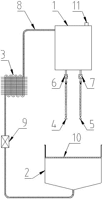
[0019] Such as figure 1 As shown, the present invention provides a cooling device for a vertical drilling machine for drilling the lug holes of the fork of the drive shaft, including a cooling liquid storage tank 1, a cooling liquid recovery bucket 2, a cooler 3 and a control system. The coolant storage tank 1 is used to store the low-temperature coolant after natural cooling. Specifically, the coolant storage tank 1 is a relatively closed box structure to ensure the relative purity of the coolant. During specific implementation, the coolant can be stored The box 1 is suspended on the vertical drilling machine, or independently supported by a bracket on the ground near the processing site. The coolant recovery bucket 2 is used to collect the high-temperature coolant flowing down from the processing part, ...


PUM


Abstract

The invention discloses a vertical drilling machine cooling device for lug-hole boring of a transmission shaft flange fork. The vertical drilling machine cooling device for lug-hole boring of the transmission shaft flange fork comprises a cooling liquid storage box, a cooling liquid recycling bin, a cooler and a controlling system; a A bamboo pipe and a B bamboo pipe are arranged at the lower part of the cooling liquid storage box, and both the A bamboo pipe and the B bamboo pipe are provided with switches; a A electromagnetic valve and a B electromagnetic valve are correspondingly arranged between the A bamboo pipe and the B bamboo pipe and the cooling liquid storage box; the cooling liquid storage box is connected with the cooling liquid recycling bin through a pipeline, and the cooler and a circulating pump are arranged on the pipeline; the upper end of the cooling liquid recycling bin is movably sleeved with a filter, and the upper end of the cooling liquid recycling bin is of a ladder-like structure; the upper end of the cooling liquid recycling bin is movably sleeved with the filter through the ladder-like structure; and the controlling system is connected with the A electromagnetic valve, the B electromagnetic valve and the circulating pump separately. The vertical drilling machine cooling device for lug-hole boring of the transmission shaft flange fork has the characteristics that the structure is simple, using is convenient, the cooling effect is good, energy is saved, and cooling and temperature reducing can be effectively conducted on lug-hole machining parts of the flange fork.

Description

technical field [0001] The invention belongs to the technical field of transmission shaft production, and relates to a transmission shaft fork, in particular to a vertical drilling machine cooling device for drilling ear holes of the transmission shaft fork. Background technique [0002] The transmission shaft is a rotating body with high speed and few supports. There are many types of transmission shafts on the market, and the application range is also very wide. The transmission shaft is mainly composed of a shaft tube, a telescopic sleeve and a universal joint. The shaft tube is located inside the telescopic sleeve. It plays the role of support and connection. The telescopic sleeve can slide relatively along the shaft tube to automatically adjust the distance between the transmission and the drive axle. The universal joint is located at both ends of the transmission shaft, one end is connected with the shaft tube or telescopic sleeve, and the other One end is connected to...

Claims


Application Information

Patent Timeline
Patent Type & Authority Applications(China)
IPC IPC(8): B23Q11/10
CPCB23Q11/10
Inventor 尚亚民
Owner HENAN XINZHOU TRANSMISSION MACHINERY CO LTD
Why Eureka
Try Eureka