Limiting type suspending cushion assembly
A suspension cushion and assembly technology, applied in the direction of power plant, jet propulsion device, internal combustion propulsion device, etc., can solve the problems of bulky structure, poor versatility, and inability to limit three-dimensional positions, and achieve overall weight reduction, light structure, The effect of enhancing versatility
- Summary
- Abstract
- Description
- Claims
- Application Information
AI Technical Summary
Problems solved by technology
Method used
Image

Examples
Embodiment 1
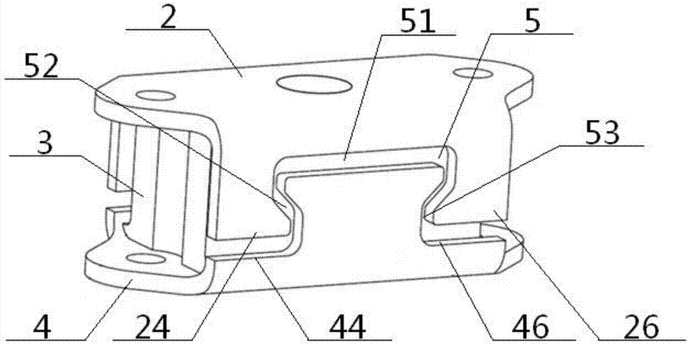
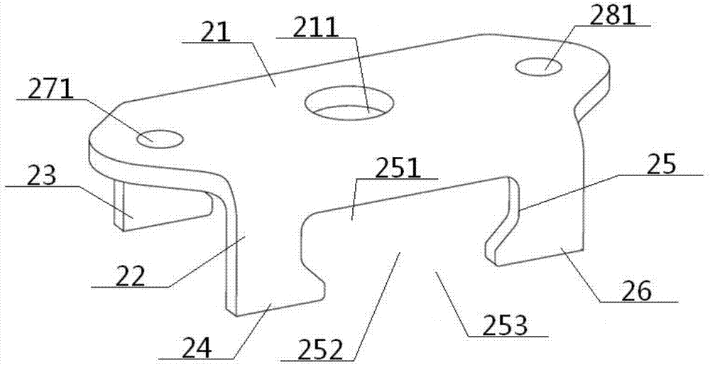
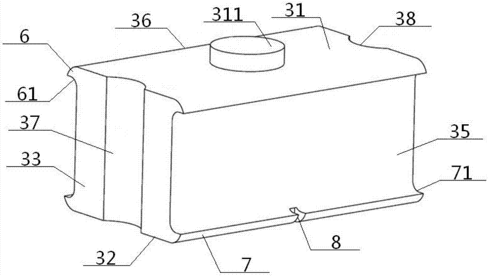
[0052] See Figure 1 to Figure 6 , A limit type suspension cushion assembly, comprising an upper frame 2, a middle rubber body 3 and a lower frame 4, the middle rubber body 3 is located between the upper frame 2, the lower frame 4, and the upper frame 2, the middle The rubber body 3 and the lower frame 4 are vulcanized into an integrated structure; the upper frame 2 includes an upper top plate 21 and an upper front side plate 22 and an upper rear side plate 23 connected to both sides thereof. The lower frame 4 includes a lower bottom plate 41 and The lower front side plate 42 and the lower rear side plate 43 connected to both sides thereof; the middle rubber body 3 is a cube structure, including a middle top surface 31, a middle bottom surface 32, a middle left side surface 33, a middle right side surface 34, The middle front side 35 and the middle rear side 36, and the middle top surface 31 and the middle bottom surface 32 are parallel to each other, the middle left side 33 an...
Embodiment 2
[0054] The basic content is the same as Example 1, the difference is:
[0055] The upper groove 25 includes an upper wide cavity 251, a middle cone cavity 252, and a lower narrow cavity 253 that communicate sequentially from top to bottom. The diameter of the middle cone cavity 252 gradually narrows from top to bottom, and the upper wide cavity The diameter of 251 is greater than the diameter of the lower narrow cavity 253; the lower bump 45 includes a lower narrow portion 451, a middle cone portion 452, and an upper wide portion 453 connected from bottom to top in sequence, and the middle cone portion 452 has a diameter from bottom to top. The diameter of the lower narrow portion 451 is smaller than the diameter of the upper wide portion 453; there is an upper gap 51 between the upper wide cavity 251 and the upper wide portion 453 located inside, and the middle cone cavity 252 is connected to the upper wide portion 453. There is a middle gap 52 between the middle taper portion 4...
Embodiment 3
[0057] The basic content is the same as Example 1, the difference is:
[0058] The left and right ends of the upper top plate 21 are respectively provided with a convex upper left convex portion 27 and an upper right convex portion 28. The upper left convex portion 27 and the upper right convex portion 28 are respectively provided with upper left bolt holes 271 and Right bolt hole 281, the left and right ends of the lower bottom plate 41 are respectively provided with a lower left convex portion 47 and a lower right convex portion 48 which are convex, respectively. The lower left convex portion 47 and the lower right convex portion 48 are respectively provided with a lower left Bolt hole 471, lower right bolt hole 481. The middle left side surface 33 and the middle right side surface 34 are respectively provided with a concave left bolt groove 37 and a right bolt groove 38. The left bolt groove 37 is connected to the upper left bolt hole 271 and the lower left bolt hole 471. The...
PUM
 Abstract
Description
Claims
Application Information
 - R&D
- Intellectual Property
- Life Sciences
- Materials
- Tech Scout
- Unparalleled Data Quality
- Higher Quality Content
- 60% Fewer Hallucinations
Browse by: Latest US Patents, China's latest patents, Technical Efficacy Thesaurus, Application Domain, Technology Topic, Popular Technical Reports.
© 2025 PatSnap. All rights reserved.Legal|Privacy policy|Modern Slavery Act Transparency Statement|Sitemap|About US| Contact US: help@patsnap.com