
Improved type air suspension

An air suspension, an improved technology, applied in the direction of suspension, elastic suspension, interconnection system, etc., can solve the problems of increasing the weight and cost of the braking system, increasing the number of air storage tanks, and narrow air storage tank layout space, etc. Achieve the effect of reducing machining accuracy, reducing installation height and reducing assembly

Active Publication Date: 2017-11-07
JIANGSU TANGCHEN AUTOMOBILE PARTS
View PDF9 Cites 4 Cited by
  • Summary
  • Abstract
  • Description
  • Claims
  • Application Information

AI Technical Summary

Problems solved by technology

However, the increase in the number of air storage tanks will lead to the following problems: increase the weight and cost of the braking system; in short-wheelbase models or models with many system configuration parts, such as tractors, the air storage tanks are arranged in a narrow space or difficult to arrange.
But, it still has certain defectives in the process of using: the height of its airbag connection panel is done relatively high, and the airbag connection panel is used for installing the airbag usefulness, so add the airbag connection panel plus the airbag The height is relatively high, and the overall structure will be relatively high, not only inconvenient to install, but also unstable in structure

Method used


Image

  • Improved type air suspension
  • Improved type air suspension
  • Improved type air suspension

Examples


Embodiment Construction

[0059] The following examples can enable those skilled in the art to understand the present invention more comprehensively, but the present invention is not limited to the scope of the described examples.

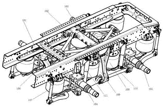
[0060] Such as Figure 1-Figure 14 A modified air suspension is shown, including

[0061] A pair of symmetrically arranged longitudinal beams 101 have several connection holes on the longitudinal beams 101 .

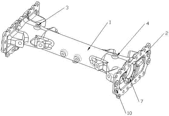
[0062] A beam 103 installed between two longitudinal beams, such as Figure 2-Figure 5 As can be seen from the schematic diagram shown, the beam 103 includes

[0063] A beam main body, the beam body is integrally cast from a beam tube body 1 and a pair of longitudinal beam connecting flanges 2 symmetrically arranged at both ends of the beam tube body 1, and the outer wall of the beam tube body 1 is integrally cast V-shaped push seat group, the beam tube body 1 is a tubular structure with two ends open, and at the two ends of the beam tube body 1 in the long axis di...


PUM


Abstract

The invention relates to an improved type air suspension. The improved type air suspension comprises a pair of longitudinal beams arranged symmetrically, a transversal beam, a pair of vehicle axles, four pairs of air bags, a pair of suspension supports, two pairs of shock absorbers and a pair of connecting lining plates, wherein a plurality of connecting holes are formed in the longitudinal beams; the transversal beam is installed between the two longitudinal beams and comprises a transversal beam main body, and the transversal beam main body is formed by one-piece casting for a transversal beam tube body and a pair of longitudinal beam connecting flanges, wherein the longitudinal beam connecting flanges are symmetrically arranged at the two ends of the transversal beam tube body; the pair of vehicle axles is installed at the lower ends of the longitudinal beams, and the two ends of the vehicle axles are fixed through supporting arms; the four pairs of air bags are correspondingly installed on airbag connection panels; the pair of suspension supports is arranged at the two outer side ends of the longitudinal beams; the two pairs of shock absorbers are correspondingly arranged at the two ends of the suspension supports; and the pair of connecting lining plates is arranged in the longitudinal beams. The improved type air suspension has the advantages that sealing performance of the transversal beam can be improved on the basis of the air supplying, and the structural strength of the transversal beam is ensured, meanwhile, manufacturing is more convenient, overall structure height can be reduced, so that the structure is more stable.

Description

technical field [0001] The invention relates to the field of automobile manufacturing, in particular to an improved air suspension. Background technique [0002] Since the birth of air suspension in the mid-nineteenth century, it has experienced a century of development and experienced "pneumatic spring-airbag composite suspension → semi-active air suspension → central inflation and deflation suspension (ie ECAS electronically controlled air suspension) system)” and many other variants. It was not until the 1950s that it was applied to trucks, buses, cars and railway locomotives. At present, almost all foreign high-end buses use air suspension, and the proportion of heavy-duty trucks using air suspension has reached more than 80%, and the application of air suspension on light vehicles is also rising rapidly. Some cars are gradually installed with air suspension. On some special vehicles (such as instrument vehicles with high requirements for shock resistance, ambulances, ...

Claims


Application Information

Patent Timeline
IPC IPC(8): B62D21/02B60G11/28B60G21/055
CPCB62D21/02B60G11/28B60G21/0551B60G2204/126B60G2202/152
Inventor 李强李培浩朱亮亮邓丽华赵双
Owner JIANGSU TANGCHEN AUTOMOBILE PARTS
Learn More